|
|
|
CHAPTER 2: HYDROLOGIC PRINCIPLES |
|
"Discharge by wells must be balanced by an increase in the recharge of the aquifer, or by a decrease in the old natural discharge, or by a loss of storage, or by a combination of these." Charles V. Theis (1940) |
|
This chapter is divided into four sections. Section 2.1 deals with precipitation, its meteorological aspects, quantitative description, spatial and temporal variations, and data sources. Section 2.2 discusses hydrologic abstractions that are important in engineering hydrology: interception, infiltration, surface storage, evaporation, and evapotranspiration. Section 2.3 defines geometric and other catchment properties relevant to hydrologic analysis. Section 2.4 deals with runoff analysis, both in a qualitative and quantitative way. The concepts presented in this chapter are of an introductory nature, intended to provide the necessary background for the more specialized study that will follow. |
2.1 PRECIPITATION
|
|
2.2 HYDROLOGIC ABSTRACTIONS
|
|
2.3 CATCHMENT PROPERTIES
|
|
Surface runoff in catchments occurs as a progression of the following forms, from small to large:
- Overland flow,
- Rill flow,
- Gully flow,
- Streamflow, and
- River flow.
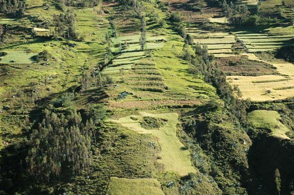
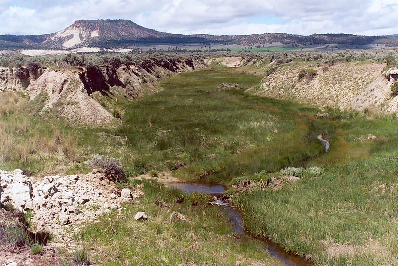
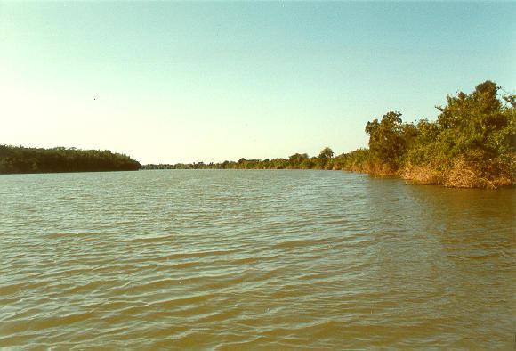
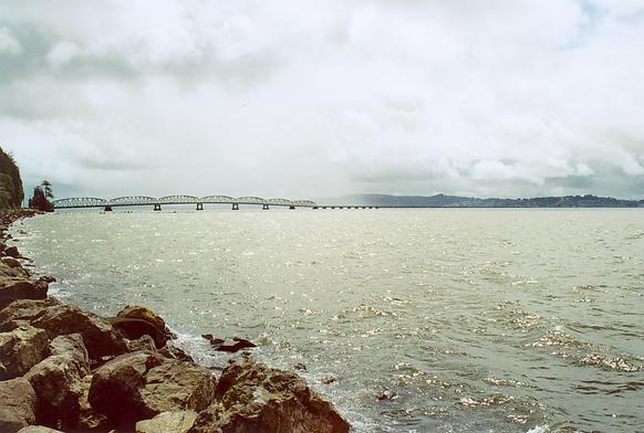
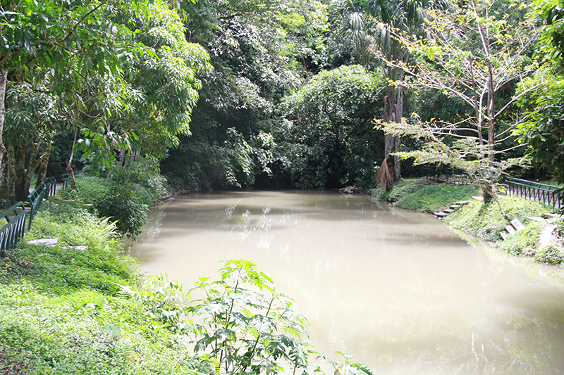
Overland flow is runoff that occurs during or immediately after a storm, in the form of sheet flow over the land surface [Fig. 2-30 (a)]. Rill flow is runoff that occurs in the form of small rivulets, primarily by concentration of overland flow. Gully flow is runoff that has concentrated into depths large enough so that it has the erosive power to carve its own deep and narrow channel (b). Streamflow is concentrated runoff originating in overland flow, rill flow, or gully flow and is characterized by well defined channels or streams of sizable depth (c). Streams carry their flow into larger streams, which flow into rivers to constitute river flow (d).
|
| ||||
|
|
A catchment can range from as little as 1 ha (or acre) to millions of square kilometers (or square miles). Small catchments (small watersheds) are those where runoff is primarily controlled by overland flow processes. Large catchments (river basins) are those where runoff is controlled by storage processes in the river channels. Between small and large catchments, there is a wide range of catchment sizes with runoff characteristics falling somewhere between those of small and large catchments. Depending on their relative size, midsize catchments are referred to as either watersheds or basins.
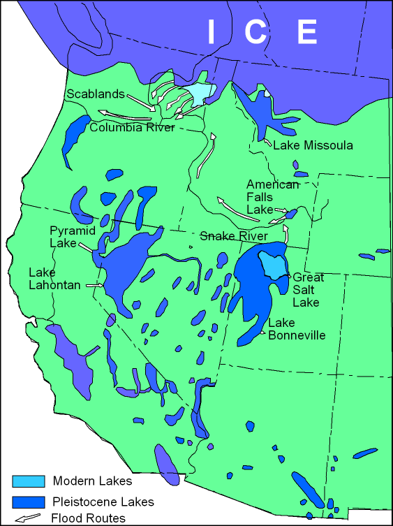
Regardless of their size, catchments can drain either inwards, into lakes (or seasonally dry lakes in arid regions), or outwards, toward the ocean. Catchments draining inwards have endorheic (or inland continental) drainages (Fig. 2-31). Catchments draining outwards have exorheic (or peripheral continental) drainages. Exorheic drainages have a catchment outlet or mouth at the point of delivery to the next largest stream, and ultimately, to the ocean.
Fig. 2-31 The Great Basin, the largest endorheic basin |
The hydrologic characteristics of a catchment are described in terms of the following properties:
Catchment Area
Area, or drainage area, is perhaps the most important catchment property. It determines the potential runoff volume, provided the storm covers the whole area. The catchment divide is the loci of points delimiting two adjacent catchments, i.e., the collection of high points separating catchments draining into different outlets. Due to the effect of subsurface flow (groundwater flow), the hydrologic catchment divide may not strictly coincide with the topographic catchment divide (Fig. 2-32). The hydrologic divide, however, is less tractable than the topographic divide; therefore, the latter is preferred for practical use.
Fig. 2-32 The Huallaga river coming out of the ground, near Tingo Maria, Peru. |
The topographic divide is delineated on a quadrangle sheet or other suitable topographic map. The direction of surface runoff is perpendicular to the contour lines. All peaks and saddles are identified at the outset (Fig. 2-33). Runoff from a peak is in all directions; runoff from a saddle is in the two opposing directions perpendicular to the saddle axis. The catchment divide is delineated by joining peaks and saddles with a line which remains perpendicular to the topographic contour. The area enclosed within the topographic divide is measured to determine the catchment area.
Fig. 2-33 Delineation of watershed boundary in Campo Creek, Southeast San Diego County, |
In general, the larger the catchment area, the greater the amount of surface runoff and, consequently, the greater the surface flows. Several formulas have been proposed to relate peak flow to catchment area (Chapter 7). A basic formula is:
|
Qp = cp An | (2-49) |
in which Qp = peak flow, A = catchment area, and c and n are parameters to be determined by regression analysis. Other peak flow methods base their calculations on peak flow per unit area, for instance, the TR-55 method (Chapter 5).
Catchment Shape
Catchment shape is the outline described by the horizontal projection of a catchment. Horton [28] described the outline of a normal catchment as a pear-shaped ovoid. Large catchments, however, vary widely in shape. A quantitative description is provided by the following formula [26]:
|
A Kf = _______ L 2 | (2-50) |
in which Kf = form ratio, A = catchment area, and L = catchment length, measured along the longest watercourse. Area and length are given in consistent units such as square kilometers and kilometers, respectively.
An alternate description is based on catchment perimeter rather than area. For this purpose, an equivalent circle is defined as a circle of area equal to that of the catchment. The compactness ratio is the ratio of the catchment perimeter to that of the equivalent circle. This leads to:
|
0.282 P Kc = ____________ A 1/2 | (2-51) |
in which Kc = compactness ratio, P = catchment perimeter, and A = catchment area, with P and A given in any consistent set of units.
Hydrologic response refers to the relative concentration and timing of runoff (Fig. 2-34). The role of catchment shape in hydrologic response has not been clearly established. Other things being equal, a high form ratio (Eq. 2-50) or a compactness ratio close to 1 (Eq. 2-51) describes a catchment having a fast and peaked catchment response. Conversely a low form ratio or a compactness ratio much larger than 1 describes a catchment with a delayed runoff response. However, many other factors, including catchment relief, vegetative cover, and drainage density are usually more important than catchment shape, with their combined effect not being readily discernible.
Fig. 2-34 Hydrologic response of La Leche river basin, Lambayeque, Peru. |
Catchment Relief
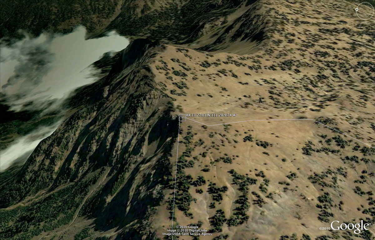
Relief is the elevation difference between two reference points. Maximum catchment relief is the elevation difference between the highest point in the catchment divide (Fig. 2-35) and the catchment outlet. The principal watercourse (or main stream) is the central and largest watercourse of the catchment and the one conveying the runoff to the outlet. Relief ratio is the ratio of maximum catchment relief to the catchment's longest horizontal straight distance measured in a direction parallel to that of the principal watercourse. The relief ratio is a measure of the intensity of the erosional processes active in the catchment.
Fig. 2-35 Highest point in the Missouri river basin,
along the border between Montana and Idaho, |
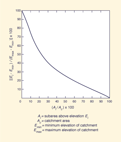
The overall relief of a catchment is described by hypsometric analysis [52]. This refers to a dimensionless curve
showing the variation with elevation of the catchment subarea above that elevation (Fig. 2-36). To develop this curve, the
elevation of the highest or maximum point in the catchment divide, corresponding to 0 percent area, is identified.
Also, the elevation of the lowest or minimum point of the catchment, corresponding to 100 percent area, is
identified. Subsequently, several elevations located between maximum and minimum are selected, and the subareas
above each one of these elevations determined by measuring along the respective topographic contour lines. The
elevations are converted to height above minimum elevation and expressed in percentage of the
maximum height. Likewise, the subareas above each one of the elevations are expressed as percentages of total
catchment area. The hypsometric curve shows percent area in the abscissas and percent height in the
ordinates (Fig. 2-36). The median elevation of the catchment is obtained from the percent height corresponding to 50 percent area.
Fig. 2-36 A hypsometric curve. |
The hypsometric curve is used when a hydrologic variable such as precipitation, vegetative cover, or snowfall shows a marked tendency to vary with altitude. In such cases, the hypsometric curve provides the quantitative means to evaluate the effect of altitude.
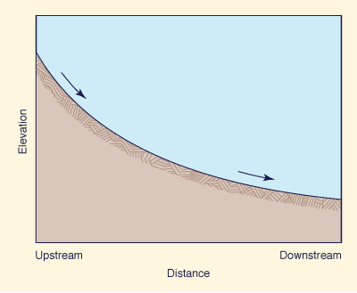
Other measures of catchment relief are based on stream and channel characteristics. The longitudinal profile of a channel is a plot of elevation versus horizontal distance (Fig. 2-37). At a given point in the profile, the elevation is usually a mean value of the channel bed. Between any two points, the channel gradient (or channel slope) is the ratio of elevation difference to horizontal distance separating them.
Fig. 2-37 Typical shape of the longitudinal profile of streams and rivers. |
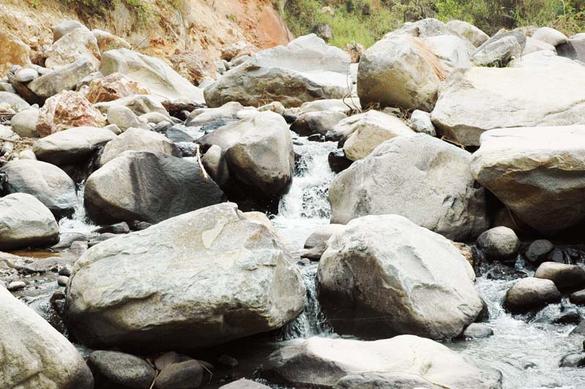
In the absence of geologic controls, longitudinal profiles of streams and rivers are usually concave upward, i.e. , they show a persistent decrease in channel gradient in the downstream direction as the flow moves from mountain streams to river valleys and into the ocean (Fig. 2-37). The reason for this downstream decrease in channel gradient requires careful analysis. It is known that channel gradients are directly related to bottom friction and inversely related to flow depth. Typically, small mountain streams have high values of bottom friction (due to the presence of cobbles and boulders in the stream bed) and small depths [[Fig. 2-38 (a)]. Conversely, large rivers have comparatively lower values of bottom friction and larger depths [Fig. 2-38 (b)]. This interaction of channel gradient and bottom friction helps explain the typical decrease in channel gradient in the downstream direction.
|
|
|
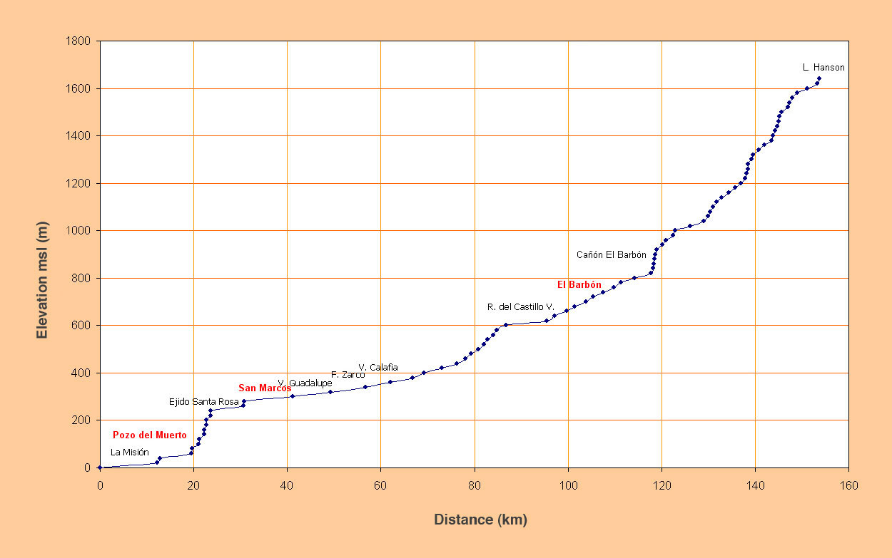
Convex channel bed profiles (Fig. 2-39) are caused by tectonism, uplift, geologic controls, or rock outcrops predominating over an otherwise alluvial channel morphology in equilibrium. These convex stream profiles usually lead to sediment deposition upstream of the outcrop, and to erosion immediately downstream.
Fig. 2-39 Bed profile of El Barbon-Guadalupe Creek, Baja California, Mexico. |
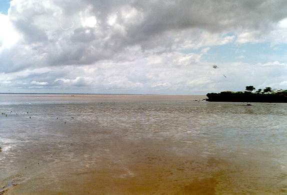
Channels gradients are usually expressed in dimensionless units. For convenience, they can be also expressed in m km-1, cm km-1, or ft mi-1. In nature, channel gradients vary widely, from higher than 0.1 in very steep mountain streams [see, for instance, Fig. 2-38 (a)], to less than 0.000006 in large tidal rivers [19].
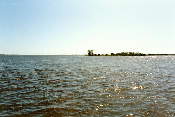
In unusual geomorphological settings, inland rivers
may feature very small channel gradients; for instance, the Upper
Paraguay river near Porto Murtinho,
Brazil, which
has an average channel slope of
2 cm km-1 (0.00002) (Fig. 2-40).
Fig. 2-40 Upper Paraguay river near Porto Murtinho, Brazil. |
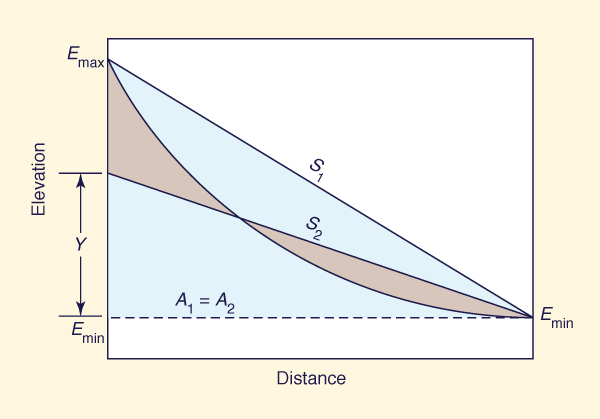
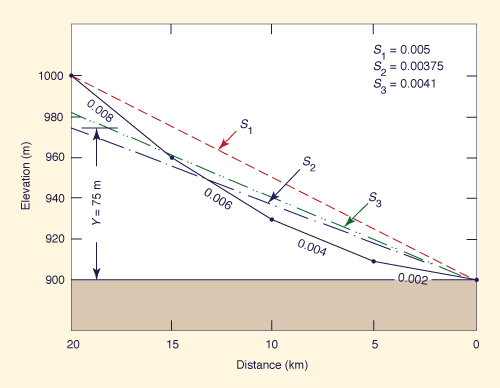
The channel gradient of a principal watercourse is a convenient indicator of catchment relief. A longitudinal profile is defined by its maximum (upstream) and minimum (downstream) elevations, and by the horizontal distance between them (Fig. 2-41). The channel gradient obtained directly from the upstream and downstream elevations is referred to as the S1 slope.
A somewhat more representative measure of channel gradient is the S2 slope, defined as the constant slope that
makes the shaded area above it equal to the shaded area below it (Fig. 2-41). An expedient way to calculate the
S2 slope is to equate the total area below it to the total area below the longitudinal profile.
Fig. 2-41 Sketch of S1 and S2 channel gradients. |
A measure of channel gradient which takes into account the basin response time is the equivalent slope, or S3. To calculate this slope the channel is divided into n subreaches, and a slope is calculated for each subreach. Based on Manning's equation (Section 2.4), the time of flow travel through each subreach is assumed to be inversely proportional to the square root of its slope. Likewise, the time of travel through the whole channel is assumed to be inversely proportional to the square root of the equivalent slope. This leads to the following equation:
|
n Σ Li i = 1 S3 = [ _______________ ] 2 n Σ ( Li / Si 1/2 ) i = 1 | (2-52) |
in which S3 = equivalent slope, Li = each i of n subreach lengths, and Si = each i of n subreach slopes.
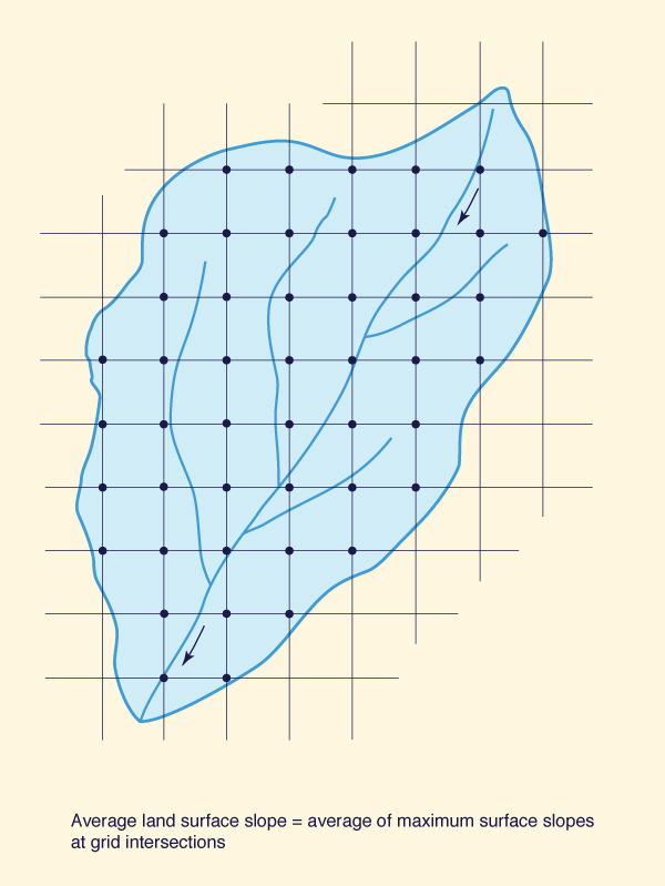
Grid methods are often used to obtain measures of land surface slope for runoff evaluations in small and midsize catchments. For instance, the USDA Natural Resources Conservation Service determines average surface slope by overlaying a square grid pattern over the topographic map of the watershed [79]. The maximum surface slope at each grid intersection is evaluated, and the average of all values calculated. This average is taken as the representative value of land surface slope (Fig. 2-42).
Fig. 2-42 Grid overlay to determine land surface slope. |
Example 2-9.
|
Fig. 2-43 Sketch of S1 and S2 channel gradients. |
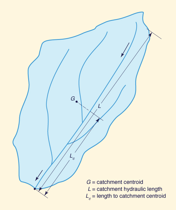
Linear measures are used to describe the one-dimensional features of a catchment. For instance, for small catchments, the overland flow length Lo is the distance of surface runoff that is not confined to any clearly defined channel.
The catchment length (or hydraulic length) L is the length measured along the principal watercourse (Fig. 2-44). The principal watercourse (or main stream) is the central and largest watercourse of the catchment and the one conveying runoff to the outlet.
Fig. 2-44 Linear measures of a catchment. |
The length to catchment centroid Lc is the length measured along the principal watercourse, from the catchment outlet to a point located closest to the catchment centroid (point G in Fig. 2-44). In practice, the catchment centroid is estimated as the intersecting point of two or more straight lines that bisect the catchment area in approximately equal subareas.
Basin Topology
Basin topology refers to the regional anatomy of the stream network. Distributed rainfall-runoff modeling (Chapter 10) requires the hierarchical description of stream connectivity, i.e., of its topology.
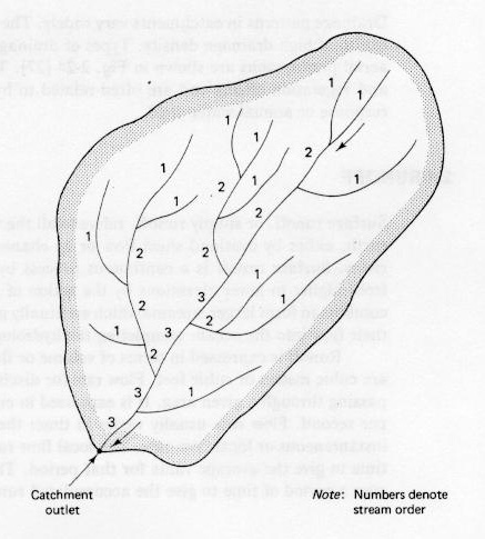
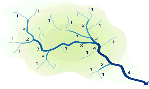
Stream Order. The concept of stream order classifies streams in a network following a hierarchical numbering system. Overland flow can be considered as a hypothetical stream of zero order. A first-order stream is that receiving flow from zero-order streams, i.e., overland flow. Two first-order streams combine to form a second-order stream. In general, two m-order streams combine to form a stream of order m + 1. The catchment's stream order is the order of the most-downstream main stem (Fig. 2-45).
|
|
Fig. 2-45 Concept of stream order.
A catchment's stream order is directly related to its size. Large catchments have stream orders of 10 or more. The evaluation of stream order is highly sensitive to map scale. Therefore, considerable care is needed when using stream order analysis in comparative studies of catchment behavior.
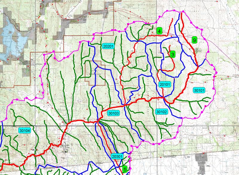
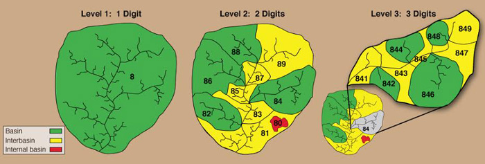
Pfasfstetter Coding System. The Pfafstetter coding system is a widely accepted methodology for the description of watershed/basin topology [**]. The system describes the regional anatomy of a stream network using a hierarchical arrangement of decimal digits.
A Level 0 catchment corresponds to a continental-scale size or, alternatively, one that drains into the ocean. Higher levels (greater than 0) represent progressively finer subdivisions of the Level 0 catchment. Theoretically, the system is not limited in the number n of levels. In practice, however, n = 6 to 8 levels are usually sufficient. At each level, each watershed is assigned a specific integer m, varying from m = 0 to 9, based on its location and function within the drainage network.
In the Pfafstetter coding system, watersheds are assigned into three categories: (a) basins, (b) interbasins, and (c) internal basin. A basin is a watershed that does not have upstream flow coming into it. An interbasin is a watershed that receives flow from other watersheds (basins and/or interbasins). An internal basin is a watershed that does not have flow coming out of it, i.e., an endorheic or closed basin. For each level, from 1 to n, the assignment of Pfafstetter codes is performed as follows:
From the catchment outlet, trace upstream along the main stem, and identify the four (4) tributaries with the largest drainage areas. The watersheds containing these four tributaries are classified as basins and assigned even digits (m = 2, 4, 6, and 8) from downstream to upstream.
The intervening watersheds, i.e., those contributing lateral inflow to the main stem, are classified as interbasins and assigned odd digits (m = 1, 3, 5, and 7) from downstream to upstream.
The last odd digit m = 9 is reserved for the headwater watershed, beyond basin 8. In general, basin 9 should be larger than basin 8; if not, their numbers are switched.
The largest internal basin, if present, is assigned the number 0. Other internal basins, if present, are incorporated into neighboring basins or interbasins.
Figure 2-46 shows a 3-level example of the Pfasfstetter coding system. For each level, say Level 3, the assigned digits (XYm) are appended on to the Level 2 code (XY). For instance, watershed 849 is watershed 8 of Level 1 (coarser), watershed 4 of Level 2 (intermediate), and watershed 9 of Level 3 (finer).
|
Fig. 2-46 The Pfafstetter coding system for watershed identification.
Drainage Density
The catchment's drainage density is the ratio of total stream length (the sum of the lengths of all streams) to catchment area. A high drainage density reflects a fast and peaked runoff response, whereas a low drainage density is characteristic of a delayed runoff response.
The mean overland flow length is approximately equal to half the mean distance between stream channels. Therefore, it can be approximated as one-half of the reciprocal of drainage density:
|
1 Lo = _______ 2D | (2-53) |
in which Lo = mean overland flow length, and D = drainage density. This approximation neglects the effect of ground and channel slope, which makes the actual mean overland flow length longer than that estimated by Eq. 2-53. The following equation can be used to estimate overland flow length more precisely:
|
1 Lo = _________________________ 2D [ 1 - (Sc /Sc) ] 1/2 | (2-54) |
in which Sc = mean channel slope, and Ss = mean surface slope.
Drainage Patterns
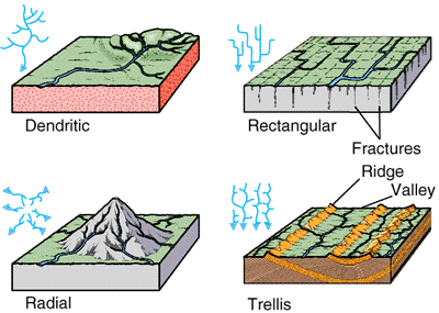
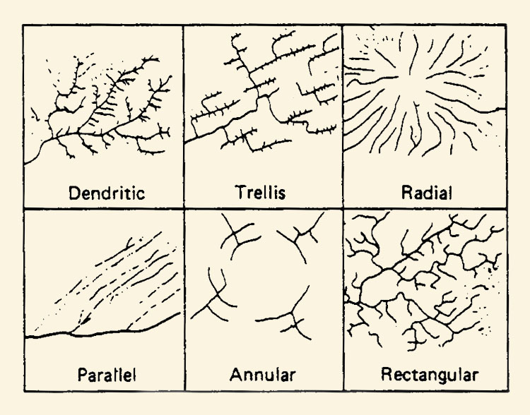
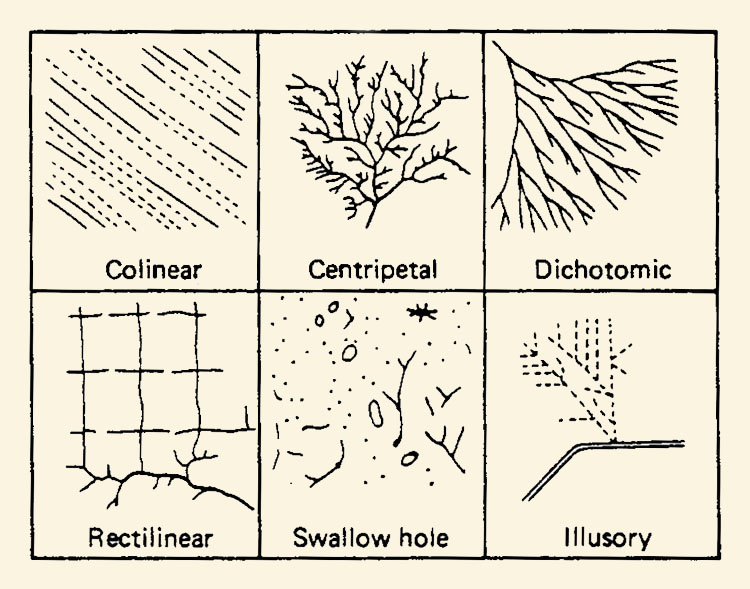
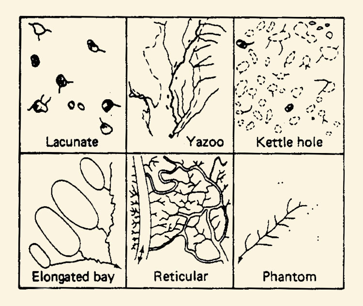
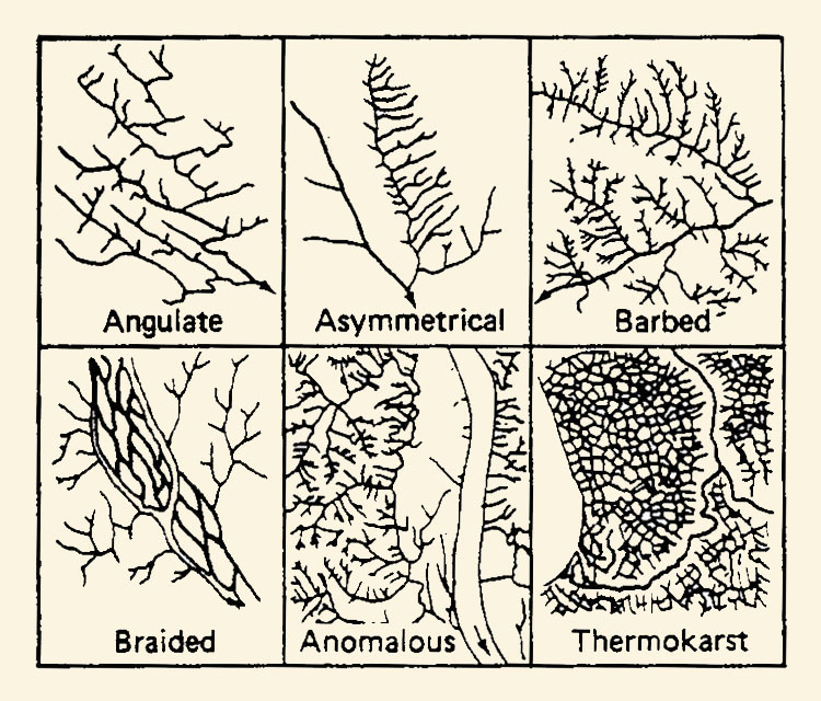
Drainage patterns in catchments vary widely. The more intricate patterns are an indication of high drainage density. Drainage patterns reflect geologic, soil, and vegetation effects (Fig. 2-47) and are often related to hydrologic properties such as runoff response or annual water yield. Types of drainage patterns that are recognizable on aerial photographs are shown in Fig. 2-48 [30].
Fig. 2-47 Drainage patterns as affected by geologic features. |
|
|
| ||||
|
|
Fig. 2-48 Drainage patterns recognizable on aerial photographs.
2.4 RUNOFF
|
|
Surface runoff, or simply runoff, refers to all the waters flowing on the surface of the earth, either by overland sheet flow or by channel flow in rills, gullies, streams, or rivers. Surface runoff is a continuous process by which water is constantly flowing from higher to lower elevations by the action of gravitational forces. Small streams combine to form larger streams which eventually grow into rivers. In time, rivers carry their flow into the ocean, completing the hydrologic cycle.
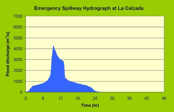
Runoff is expressed in terms of volume or flow rate. The units of runoff volume are cubic meters or cubic feet. Flow rate (or discharge) is the volume per unit of time passing through a given area. It is expressed in cubic meters per second or cubic feet per second. Flow rate usually varies in time; therefore, its value at any time is the instantaneous or local flow rate. The local flow rate can be averaged over a period of time to give the average value for that period. The local flow rate can be integrated over a period of time to give the accumulated runoff volume.
In engineering hydrology, runoff is commonly expressed in depth units. This is accomplished by dividing the runoff volume by the catchment area to obtain an equivalent runoff depth distributed over the entire catchment.
For certain applications, runoff is alternatively expressed in terms of either: (1) peak flow per unit drainage area, (2) peak flow per unit runoff depth, or (3) peak flow per unit drainage area per unit runoff depth. In the first case, the units are cubic meters per second per square kilometer; in the second case, cubic meters per second per centimeter; in the third case, cubic meters per second per square kilometer per centimeter.
Runoff Components
Runoff consists of water from three sources: (1) surface flow, (2) interflow, and (3) groundwater flow. Surface flow is the product of effective rainfall, i.e., total rainfall minus hydrologic abstractions. Surface flow is also called direct runoff. Direct runoff has the capability to produce large flow concentrations in a relatively short period of time. Therefore, direct runoff is largely responsible for flood flows. Interflow is subsurface flow , i.e., flow that takes place in the unsaturated soil layers located beneath the ground surface. Interflow consists of the lateral movement of water and moisture toward lower elevations, and it includes some of the precipitation abstracted by infiltration. It is characteristically a slow process, but eventually interflow volumes flow into streams and rivers. The quantities of interflow are relatively small compared to the quantities of groundwater flow.
Groundwater flow takes place below the groundwater table (Chapter 11) in the form of saturated flow through alluvial deposits and other water-bearing geologic formations located beneath the soil mantle. Groundwater flow includes the portion of infiltrated volume that has reached the water table by percolation from the overlying soils. Like interflow, groundwater flow is characteristically a slow process. Like surface runoff, groundwater flow is a continuous process, with water constantly moving to lower elevations (or to zones of lower potential). Most groundwater flow is eventually intercepted by streams and rivers, discharging into them. A small portion of groundwater flow, particularly that flowing at great depths, eventually makes its way into the nearest ocean.
Stream Types and Baseflow
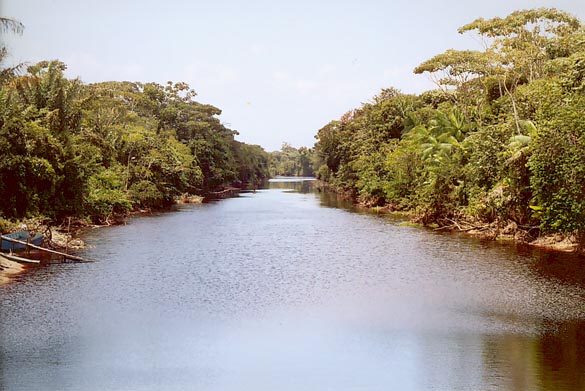
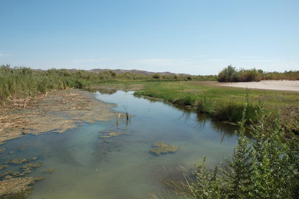
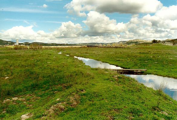
Streams may be grouped into three types: (1) perennial, (2) ephemeral, and (3) intermittent. Perennial streams are those that always have flow . During dry weather (i.e., absence of rain), the flow of perennial streams is baseflow, consisting mostly of groundwater flow intercepted by the stream. Streams that feed from groundwater reservoirs are called effluent streams. Perennial and effluent streams are typical of subhumid and humid regions [(Fig. 2-49 (a)].
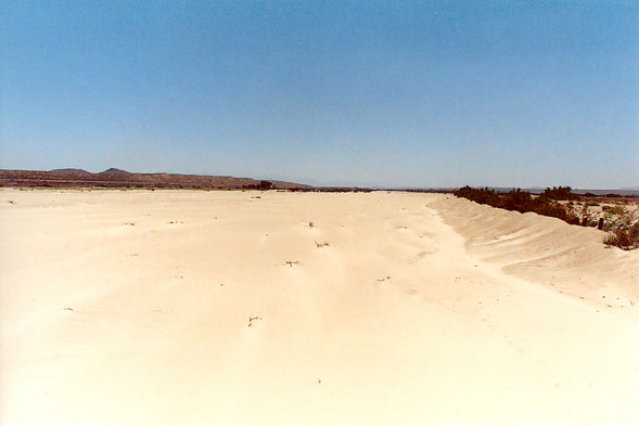
Ephemeral streams are those that have flow only in direct response to precipitation, i.e., during and immediately following a major storm. Ephemeral streams do not intercept groundwater flow and therefore have no baseflow. Instead, ephemeral streams usually contribute to groundwater by seepage through their porous channel beds. Streams that feed water into groundwater reservoirs are called influent streams. Channel abstractions from influent streams are referred to as channel transmission losses. Ephemeral and influent streams are typical of arid and semiarid regions [(Fig. 2-49 (a)].
Intermittent streams are those of mixed characteristics, behaving as perennial at certain times of the year and ephemeral at other times. Depending on seasonal conditions, these streams may feed to or from the groundwater [(Fig. 2-49 (c)].
|
|
|
Fig. 2-49 (c) Intermittent stream: |
Baseflow estimates are important in dry weather hydrology; for instance, in the calculation of the total runoff volume produced by a catchment in a year, referred to as the annual water yield. In flood hydrology, baseflow is used to separate surface runoff into direct and indirect runoff. Indirect runoff is surface runoff originating in interflow and groundwater flow. Baseflow is a measure of indirect runoff.
It is noted that surface runoff may or may not include baseflow. In practice, the term "surface runoff" is often used at the watershed scale to refer to direct runoff, which ostensibly excludes baseflow (indirect runoff). Yet, at the basin scale, estimates of surface water yield are known to include both direct and indirect runoff. The confusion is frequently a source of error in hydrologic analysis. For instance, the NRCS runoff curve number method (Chapter 5) was originally developed to calculate direct surface runoff from small watersheds. Yet, over the years since its original inception, the method has also been used to calculate surface runoff from larger watersheds, which may include baseflow.
Antecedent Moisture
Effective precipitation is the fraction of total precipitation that remains on the catchment surface after all the hydrologic abstractions have taken place. During rainy periods, infiltration plays a major role in abstracting total precipitation. Actual infiltration rates and amounts vary widely, being highly dependent on the initial level of soil moisture. Soil moisture varies with the history of antecedent rainfall, increasing with antecedent rainfall and decreasing with a lack of it. For a given storm, the history of antecedent rainfall, which may have caused the soil moisture to depart from an average state, is termed the "antecedent moisture" or "antecedent rainfall" condition. A catchment with low initial soil moisture (e.g., a catchment drier than normal) is not conducive to high surface flow and direct runoff. Conversely, a catchment with high initial soil moisture (e.g., a catchment wetter than normal) is conducive to large quantities of surface flow and direct runoff.
Fig. 2-50 A catchment with high antecedent moisture: |
The recognition that direct runoff is a function of antecedent moisture has led to the concept of antecedent precipitation index (API). The average moisture level in a catchment varies daily, being replenished by precipitation and depleted by evaporation and evapotranspiration. The assumption of a logarithmic depletion rate leads to a catchment's API for a day with no rain:
|
Ii = K Ii-1 | (2-55) |
in which Ii = index for day i, Ii-1 index for day i -1, and K = a recession factor taken normally in the range 0.85-0.98 [53]. If rain occurs in any day, the rainfall depth is added to the index. The index at day zero (initial value) would have to be estimated. Likewise, the applicable value of K is determined from either data or experience.
The API is directly related to runoff depth. The greater the value of the index, the greater the amount of runoff. In practice, regression and other statistical tools are used to relate runoff to API. These relations are invariably empirical and therefore strictly applicable only to the situation for which they were derived.
Other measures of catchment moisture have been developed over the years. For instance, the Natural Resources Conservation Service (NSCS) uses the concept of antecedent moisture condition (AMC) (Chapter 5), grouping catchment moisture into three levels: AMC I, a dry condition; AMC II, an average condition; and AMC III, a wet condition. Moisture conditions ranging from AMC II to AMC III are normally used in hydrologic design.
Another example of the use of the concept of antecedent moisture is that of the SSARR model (Chapter 13). The SSARR model computes runoff volume based on a relationship linking runoff percent to a soil-moisture index (SMI), with precipitation intensity as a third variable. Runoff percent is the ratio of runoff to rainfall, multiplied by 100. Such runoff-moisture-rainfall relation is empirical and, therefore, is limited to the basin for which it was derived.
Rainfall-Runoff Relations
Rainfall can be measured in a relatively simple way. However, runoff measurements usually require an elaborate streamgaging procedure (Chapter 3). This difference has led to rainfall data being more widely available than runoff data. The typical catchment has many more rain gages than streamgaging stations, with the rainfall records likely to be longer than the streamflow records.
The fact that rainfall data is more voluminous than runoff data has led to the calculation of runoff by relying on rainfall data. Although this is an indirect procedure, it has proven its practicality in a variety of applications.
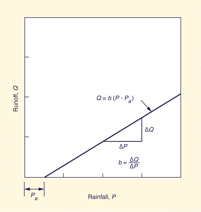
A basic linear model of rainfall-runoff is the following:
|
Q = b ( P - Pa ) | (2-56) |
in which Q = runoff depth, P = rainfall depth, Pa = rainfall depth below which runoff is zero, and b = slope of the line (Fig. 2-51). Rainfall depths smaller than Pa are completely abstracted by the catchment, with runoff starting as soon as P exceeds Pa. To use Eq. 2-56 it is necessary to collect several sets of rainfall-runoff data and to perform a linear regression (Chapter 7) to determine the values of b and Pa. The simplicity of Eq. 2-56 precludes it from taking into account other important runoff-producing mechamsms such as rainfall intensity, infiltration rates, or antecedent moisture. In practice, the correlation usually shows a wide range of variation, limiting its predictive ability.
Fig. 2-51 Basic linear model of rainfall-runoff. |
The effect of infiltration rate and antecedent moisture on runoff is widely recognized. Several models have been developed in an attempt to simulate these and other related processes. Typical of such models is the NRCS runoff curve number model, which has had wide acceptance in engineering practice. The NRCS model is based on a nonlinear rainfall-runoff relation that includes a third variable (curve parameter) called the runoff curve number, or CN. In a particular application, the CN value is determined by a detailed evaluation of soil type, vegetative and land use patterns, antecedent moisture, and hydrologic condition of the catchment surface. The NRCS runoff curve number method is described in Chapter 5.
Runoff Concentration
An important characteristic of surface runoff is its concentration property. To describe it, assume that a storm falling on a given catchment produces a uniform effective rainfall intensity distributed over the entire catchment area. In such a case, surface runoff eventually concentrates at the catchment outlet, provided the effective rainfall duration is sufficiently long. Runoff concentration implies that the flow rate at the outlet will gradually increase until rainfall from the entire catchment has had time to travel to the outlet and is contributing to the flow at that point. At that time, the maximum, or equilibrium, flow rate is reached, implying that the surface runoff has concentrated at the outlet. The time that it takes a parcel of water to travel from the farthest point in the catchment divide to the catchment outlet is referred to as the time of concentration.
The equilibrium flow rate is calculated by multiplying the effective rainfall intensity by the catchment area:
|
Qe = Ie A | (2-57) |
in which Qe = equilibrium flow rate; Ie = effective rainfall intensity; and A = catchment area. This equation is dimensionally consistent; however, a conversion factor is needed in the right-hand side to account for the chosen units. For instance, in SI units, with Qe in liters per second, Ie in millimeters per hour, and A in hectares, the conversion factor is 2.78. In U.S. customary units, with Qe in cubic feet per second, Ie in inches per hour, and A in acres, the conversion factor is 1.008, which is often neglected.
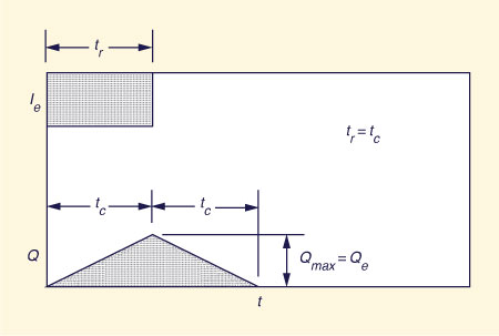
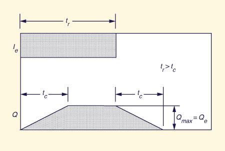
The process of runoff concentration can lead to three distinct types of catchment response. The first type occurs when the effective rainfall duration is equal to the time of concentration. In this case, the runoff concentrates at the outlet, reaching its maximum (equilibrium) rate after an elapsed time equal to the time of concentration. Rainfall stops at this time, and subsequent flows at the outlet are no longer concentrated because not all the catchment is contributing. Therefore, the flow gradually starts to recede back to zero. Since it takes the time of concentration for the farthest runoff parcels to travel to the outlet, the recession time is approximately equal to the time of concentration, as sketched in Fig. 2-52 (a). (In practice, due to nonlinearities, actual recession flows are usually asymptotic to zero). This type of response is referred to as concentrated catchment flow.
The second type of catchment response occurs when the effective rainfall duration exceeds the time of concentration. In this case, the runoff concentrates at the outlet, reaching its maximum (equilibrium) rate after an elapsed time equal to the time of concentration. Since rainfall continues to occur, the whole catchment continues to contribute to flow at the outlet, and subsequent flows remain concentrated and equal to the equilibrium value. After rainfall stops, the flow gradually recedes back to zero. Since it takes the time of concentration for the farthest runoff parcels to travel to the outlet, the recession time is approximately equal to the time of concentration; see Fig. 2-52 (b). This type of response is referred to as superconcentrated catchment flow.
|
|
|
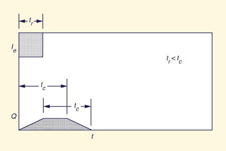
The third type of response occurs when the effective rainfall duration is shorter than the time of concentration. In this case the flow at the outlet does not reach the equilibrium value. After rainfall stops, the flow recedes back to zero. The requirements that volume be conserved and recession time be equal to the time of concentration lead to the idealized flat top response shown in Fig. 2-56 (c). This type of response is referred to as subconcentrated catchment flow.
Fig. 2-52 (c) Subconcentrated catchment flow |
In practice, concentrated and superconcentrated flows are typical of small catchments, i.e., those likely to have short times of concentration. On the other hand, subconcentrated flows are typical of midsize and large catchments, i.e., those with longer times of concentration.
QUESTIONS
|
|
Alley,
PROBLEMS
|
|
Alley,
REFERENCES
|
|
Alley, W. M., T. E. Reilly, and. O. E. Franke. 1999. Sustainability of ground-water resources. U.S. Geological Survey Circular 1186, Denver, Colorado, 79 p.
| http://engineeringhydrology.sdsu.edu | 140302 23:00 |
