|
ENGINEERING HYDROLOGY: CHAPTER 045 - OVERLAND FLOW - KINEMATIC WAVES
1. TYPES OF RATING
1.01
According to kinematic wave theory, the discharge-depth rating at any point is:
1.02
1.03
in which b = coefficient and m = exponent of the rating.
1.04
Unlike Horton's conceptual approach, which bases the rating on the storage volume on the entire plane,
the kinematic wave approach bases the rating on flow depths at individual cross sections.
1.05
This difference has substantial implications for computer modeling, because whereas the conceptual approach is lumped in space, the
kinematic wave approach is not, making it better suited to distributed computation.
1.06
The difference between a rating based on storage volume and one based on flow depth merits careful analysis.
1.07
There are two distinct features in natural catchments:
1. reservoirs, and
2. channels.
1.08

1.09
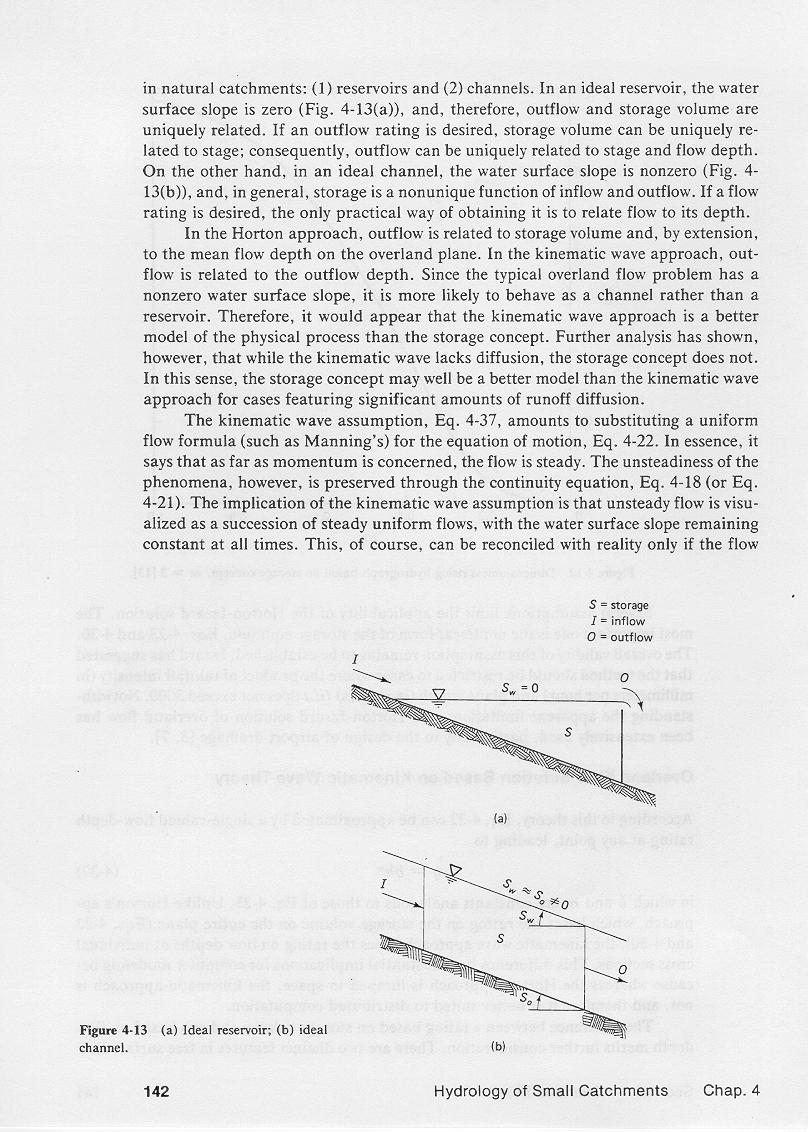
In an ideal reservoir the water surface slope is zero and, therefore, outflow and storage are uniquely related.
1.10
Storage volume can be uniquely related to stage; consequently, outflow
can be uniquely related to stage and flow depth.
1.11
On the other hand, in an ideal channel, the water surface slope is nonzero, and in general,
storage is a nonunique function of inflow and outflow.
1.12
In this case, the only practical way of obtaining a rating is to relate
discharge to its depth.
1.13
In Horton's storage approach, outflow is related to storage volume, and by extension,
to the mean flow depth on the overland flow plane.
1.14
In the kinematic wave approach, outflow is related to its flow depth.
1.15
Since the typical overland flow problem has a nonzero water surface slope,
it is more likely to behave as a channel rather than as a reservoir.
1.16
Thus, it would appear that the kinematic wave approach is a better model of the physical process than the storage concept.
1.17
Further analysis has shown, however, that while the kinematic wave lack diffusion, the storage concept does not.
1.18
In this sense, the storage concept remains applicable for cases featuring significant amounts of runoff diffusion.
2. KINEMATIC WAVES
2.01
The kinematic wave approach amounts to substituting a uniform flow formula for the equation of motion.
2.02
In essence, it says that, as far as momentum is concerned, the flow is steady!
2.03
However, the flow unsteadiness is preserved through the continuity equation.
2.04
The implication of kinematic flow is that unsteady flow can be visualized as a
succession of steady uniform flows, with the water surface slope remaining constant at all times.
2.05
This can be reconciled with reality only if the changes in stage occur very gradually.
2.06
In practice, a necessary condition for the applicability of kinematic flow is that changes in momentum be negligible compared
to the forces driving the steady flow, that is, gravity and friction.
2.07
The kinematic flow number used in overland flow applications serves as a quantitative measure of how kinematic a flow is.
3. KINEMATIC WAVE EQUATION
3.01
The equation of mass conservation, per unit of plane width, is:
3.02
3.03
in which q = unit-width discharge, h = flow depth, and i = rainfall excess.
3.04
The kinematic wave discharge-depth rating is:
3.05
3.06
Differentiating this equation with respect to h, we obtain the kinematic wave celerity:
3.07
3.08
in which u = mean flow velocity, and c = celerity of a kinematic wave.
3.09
Since m is greater than 1, the celerity of a kinematic wave is greater than the mean flow velocity.
3.10
Multiplying the equation of mass conservation with the equation for kinematic wave celerity, and applying the chain rule of differentiation, leads to the kinematic wave equation:
3.11
3.12
A similar equation for kinematic wave in terms of flow depth is:
3.13
3.14
With the characteristic celerity c = dx/dt, the left-hand side of this equation denotes the total differential dh/dt. Thus:
3.15
3.16
This equation can be integrated to yield:
3.17
3.18
which states that the flow depth at any point increases linearly with time, provided, of course, that the rainfall excess remains constant.
4. TIME TO EQUILIBRIUM
4.01
The kinematic wave overland flow solution resembles that of the storage concept, with a rising limb, an equilibrium state, and a receding limb.
4.02
The equilibrium state is the same as that of the storage concept, that is, a statement of runoff concentration.
4.03
However, the time to equilibrium is different.
4.04
To derive the overland flow kinematic wave solution, we express the discharge-depth rating at the equilibrium outflow:
4.05
4.06
where unlike the storage concept, he is now the equilibrium flow depth at the outlet.
4.07
Relating discharge at any time to the discharge at equilibrium state at the outlet:
4.08
4.09
Defining the kinematic time-to-equilibrium te as follows:
4.10
4.11
which leads to:
4.12
4.13
This equation is applicable only on the rising limb, that is, for t ≤ te
4.14
Otherwise, the flow would exceed the equilibrium value, which is clearly impossible.
4.15
By runoff concentration, the equilibrium outflow is:
4.16
4.17
For turbulent Manning friction, the coefficient of the rating is:
4.18
4.19
Combining these equations leads to the time-to-equilibrium of the kinematic wave:
4.20
n1/m L1/m
i(m-1)/m So1/(2m)
|
4.21
Note that this equation is the same as that of the storage concept, but for the factor 2 missing in the numerator.
4.22
Therefore, the time to equilibrium of the kinematic wave is one half of that of the storage concept.
4.23
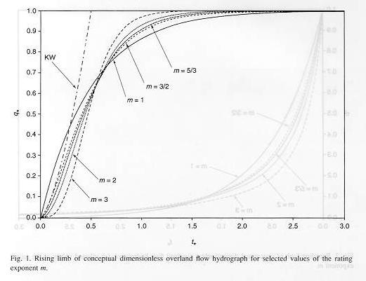
Essentially, the analytical solution of the kinematic wave is a parabola, while that of the storage concept is a hyperbolic trigonometric function.
4.24
This figure shows dimensionless rising overland flow hydrographs for the kinematic wave
and several solutions of the storage concept, with the rating exponent m varying from 1 to 3.
4.25

5. APPLICABILITY
5.01
The kinematic flow number describes the applicability of kinematic waves.
5.02
It is defined as follows:
5.03
5.04
in which F = Froude number.
5.05
5.06
in which uo = mean velocity.
5.07
Values of K > 20 describe kinematic flow.
5.08
Typically the slope Sois likely to vary within a wider range that either L, F, or ho.
5.09
Thus, whether the flow is kinematic or not depends largely on the slope.
5.10
The steeper the slope, the greater the K, and the more kinematic the flow is.
5.11
For sufficiently mild slopes, K decreases, and the flow ceases to be kinematic.
5.12
For very mild slopes, the assumption of kinematic flow is no longer justified.
5.13
Experience shows that plane slopes greater than or equal to 0.01 usually produce kinematic flow.
5.14
Conversely, slopes lesser than or equal to 0.001 are usually do not produce kinematic flow, that is, they are either diffusive or dynamic.
6. KINEMATIC SHOCK
6.01
The kinematic wave equation is nonlinear because the celerity varies with the flow.
6.02
This nonlinear property leads to a steepening tendency of the kinematic wave.
6.03
Due to the steepening, overland flow analytical solutions of the kinematic wave have a tendency to develop the shock.
6.04

6.05
In natural systems, small irregularities produce diffusion, which has the effect of counteracting the steepening.
6.06
Numerical solutions feature numerical diffusion, which also arrests the steepening.
6.07
Analytical solutions have no diffusion; therefore, an analytical solution of the kinematic wave
is poised to eventually develop the shock.
6.08
Natural systems have intrinsic built-in irregularities; thus, the kinematic shock is a rare occurrence in nature.
7. DIFFUSION WAVES
7.01
According to diffusion wave theory, the flow depth gradient is largely responsible for the diffusion mechanism.
7.02
Its inclusion in the analysis provides runoff concentration with diffusion.
7.03
The diffusion wave equation resembles the kinematic wave equation, but for the addition of a diffusion term on the right-hand side.
7.04
7.05
The applicable diffusion coefficient is Hayami's hydraulic diffusivity:
7.06
7.07
The hydraulic diffusivity is directly proportional to the unit-width discharge and inversely proportional to the plane slope.
7.08
Thus, diffusion waves apply to milder slopes, where the kinematic wave ceases to be applicable.
7.09
The diffusion wave technique provides the theoretical basis for the Muskingum-Cunge
method of flood routing used in the U.S. Army Corps of Engineers' HEC-HMS model, among others.
Narrator: Victor M. Ponce
Music: Fernando Oñate
Editor: Flor Pérez
Copyright © 2010
Visualab Productions
All rights reserved
| 

