|
ENGINEERING HYDROLOGY: CHAPTER 054 - UNIT HYDROGRAPHS
1. UNIT HYDROGRAPH
1.01
The unit hydrograph is used in midsize catchment analysis as a means to develop a hydrograph for a given storm.
1.02
The word unit is normally taken to refer to a unit depth of effective rainfall or runoff.
1.03
However, it should be noted that Sherman first used the
word to describe a unit depth of runoff, 1 cm or 1 in,
lasting a unit increment of time, that is, an indivisible increment.
1.04
The unit increment of time can be either 1 hr, 3 hr, 6 hr, 24 hr, or any other suitable duration.
1.05
For midsize catchments, unit hydrograph durations from 1 to 6 hr are in common use.
1.06
The unit hydrograph is the hydrograph produced by a unit depth of runoff uniformly distributed over the entire catchment
and lasting a specified duration.
1.07
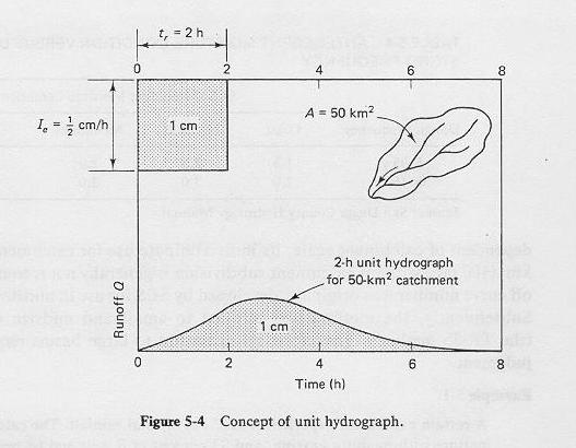
Assume that a certain storm produces 1 cm of runoff and covers a 50-km2 catchment over a 2-hr period.
1.08
1.09
The hydrograph measured at the catchment outlet would be the 2-hr unit hydrograph for this 50-km2 catchment.
1.10
A unit hydrograph for a given catchment can be calculated: (a) directly, or (b) indirectly.
1.11
The direct method uses rainfall-runoff data for selected events.
1.12
The indirect method uses a synthetic unit hydrograph formula.
1.13
While both methods can be used for gaged catchments, only the indirect method is applicable to ungaged catchments.
1.14
Most catchments are ungaged; therefore, synthetic unit hydrographs are a very useful tool in applied hydrology.
1.15
Since a given unit hydrograph is defined for a given storm duration, it follows that a catchment
can have several unit hydrographs, each for a different duration.
1.16
Once a unit hydrograph of a given duration has been obtained,
it can be used to derive unit hydrographs for other durations.
1.17
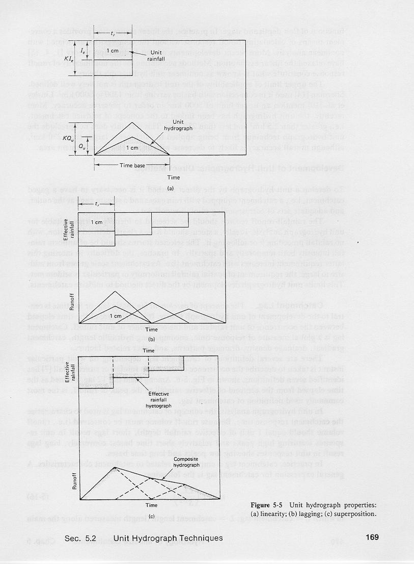
The assumptions of linearity and superposition are crucial to the development of unit hydrographs.
1.18
1.19
Linearity means that a hydrograph for a runoff depth other than unity
can be derived by simply multiplying the unit hydrograph ordinates by the indicated runoff depth.
1.20
The time base of the hydrograph remains constant regardless of runoff depth.
1.21
The procedure can be used to calculate hydrographs produced by a storm consisting of a series of runoff depths, each lagged
in time one increment of unit hydrograph duration.
1.22
Superposition enables the summation of the corresponding ordinates of these lagged hydrographs
to calculate the composite or flood hydrograph.
1.23
The procedure is referred to as the convolution of the unit hydrograph with the effective storm hyetograph.
1.24
The linearity assumption has long been considered one of the limitations of unit hydrograph theory.
1.25
In nature, it is unlikely that catchment response will always follow a linear function.
1.26
In practice, the linear assumption provides a convenient means of calculating runoff response without the complexities
associated with nonlinear analysis.
1.27
The applicability of the unit hydrograph is restricted to midsize catchments, typically greater than 2.5 km2, and less than 250 to 1000 km2.
2. CATCHMENT LAG
2.01
The concept of catchment lag, basin lag, or lag time, is essential to unit hydrograph theory.
2.02
It is a measure of the time elapsed between the occurrence of unit rainfall and the occurrence of unit runoff.
2.03
Catchment lag is a global measure of response time, encompassing
hydraulic length, catchment gradient, drainage density, and drainage pattern.
2.04
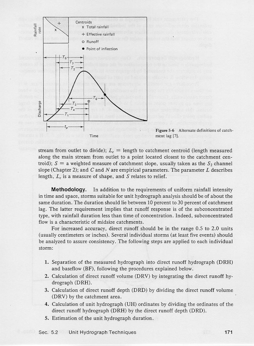
There are several definitions of catchment lag, depending on what particular instance is taken to describe the occurrence of either rainfall or runoff.
2.05
The T2 lag, defined as the time elapsed from the centroid of effective rainfall to the peak of runoff is the most commonly used definition of
catchment lag.
2.06
2.07
Because unit runoff volume must be conserved, short lags result in high peaks and short time bases; conversely, long lags result in
low peaks and long time bases.
2.08
In practice, catchment lag is empirically related to catchment characteristics.
2.09
A general formula is:
2.10
2.11
in which
tl = catchment lag;
L = hydraulic length
Lc = length measured along main stream from the outlet to a point closest to catchment centroid;
S = weighted measure of catchment slope; and
C and N = empiriral constants.
3. UNIT HYDROGRAPHS FROM MEASURED DATA
3.01
To develop a unit hydrograph from measured data, it is necessary to have a gaged catchment.
3.02
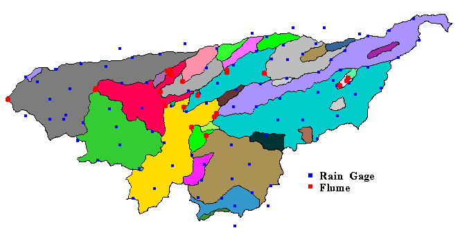
Raingages and flumes in the USDA ARS Walnut Gulch experimental watershed, near Tombstone, Arizona.
3.03
Corresponding sets of rainfall-runoff data are collected,
and storms suitable for unit hydrograph analysis are identified.
3.04
The selected storms must be of uniform rainfall intensity, both temporally and spatially, and of
about the same duration.
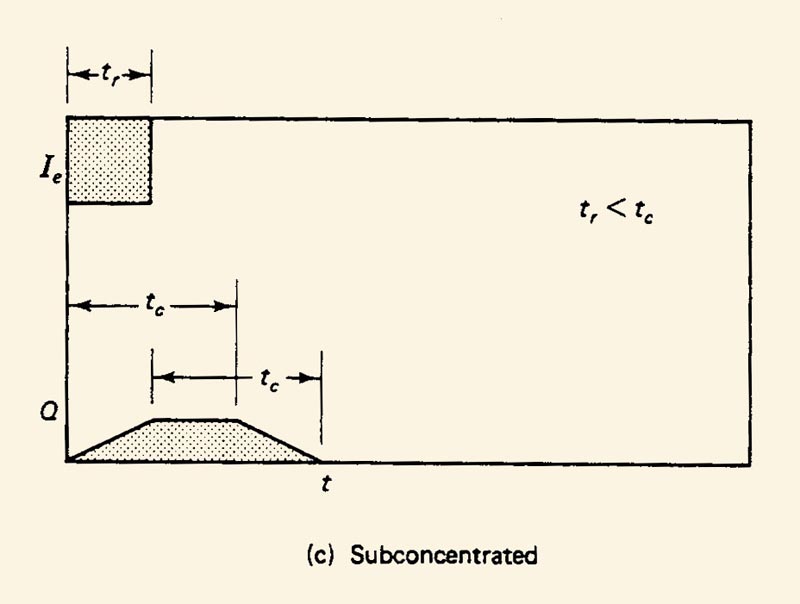
3.05
The duration should be about 10 to 30 percent of the lag.
3.06
This requirement implies that the runoff response of midsize catchments is of the subconcentrated type,
with rainfall duration less than time of concentration.
3.07
3.08
For best results, runoff should be in the range 0.5-2.0 units, either inches or centimeters.
3.08
To assure consistency, at least five events must be considered.
3.10
The following steps are applied to individual storms:
- Separation of the measured hydrograph MH into direct runoff hydrograph DRH and baseflow BF.
MH = DRH + BF
- Integration of the direct runoff hydrograph DRH, obtained in Step 1, to calculate the direct runoff volume DRV.
DRV = ∫ DRH
- Calculation of the direct runoff depth DRD by dividing the direct runoff volume DRV calculated in Step 2 by the catchment area A.
DRD = DRV / A
- Calculation of the unit hydrograph ordinates UH by dividing the ordinates of the direct runoff hydrograph DRH obtained in Step 1,
by the direct runoff
depth DRD calculated in Step 3.
UH = DRH / DRD
- Estimation of the unit hydrograph duration tr by averaging the individual durations.
3.11
The catchment unit hydrograph is obtained by averaging the unit hydrograph ordinates obtained for individual storms.
3.12
Minor adjustments may be required to ensure that the volume under the unit hydrograph is equal to one unit of runoff depth.
4. BASEFLOW SEPARATION
4.01
The procedures for baseflow separation are generally empirical.
4.02
Interflow is usually included as part of baseflow.
4.03
A point P is identified in the receding limb, where direct runoff ends.
4.04
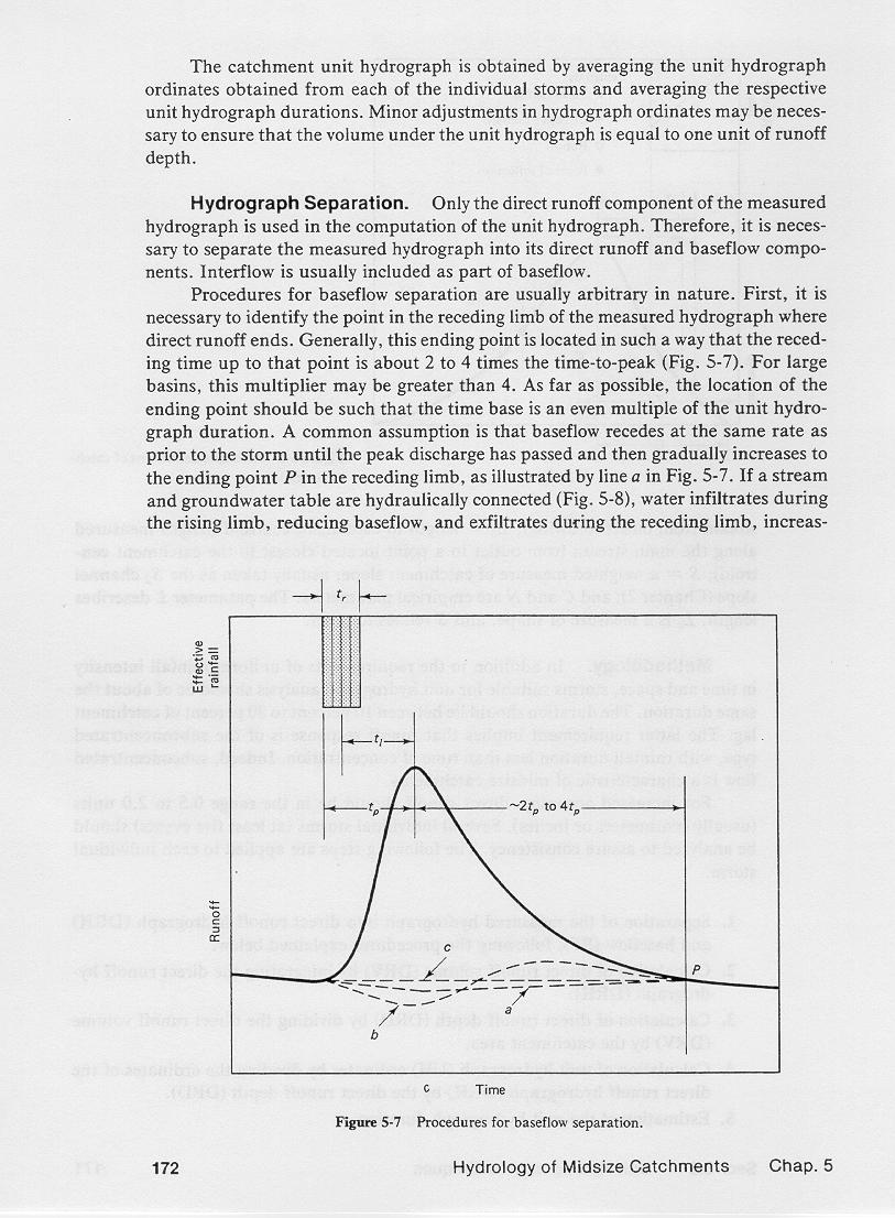
4.05
Generally, this point is located at the end of the recession, typically from about 2 to 4 times the time to peak.
4.06
For large basins, this multiplier may be greater than 4.
4.07
A common assumption for baseflow separation is that baseflow recedes at the same rate as prior to the storm
until the peak discharge has passed and then, gradually increases to the ending point P,
as shown by line a.
4.08
When the stream and groundwater table are hydraulically connected, water exfiltrates during the rising limb, reducing baseflow,
and infiltrates during the receding limb, increasing baseflow, as shown by line b.
4.09
The most expedient assumption for baseflow separation is a straight line from the start of the rising limb to
the ending point, as shown by line c.
4.10
In most cases of practical interest, differences between the various baseflow separation techniques are likely to be small.
Narrator: Victor M. Ponce
Music: Fernando Oñate
Editor: Flor Pérez
Copyright © 2011
Visualab Productions
All rights reserved
| 


