|
ENGINEERING HYDROLOGY: CHAPTER 081 - RESERVOIR ROUTING
1. RESERVOIRS
1.01
A reservoir is a natural or artificial feature which stores incoming water
and releases it at regulated rates.
1.02
Surface water reservoirs should be distinguished from natural groundwater reservoirs
which store groundwater.
1.03
Surface water reservoirs store water for diverse uses,
including hydropower generation, municipal and industrial water supply,
flood control, irrigation, navigation, fish and wildlife management,
water quality, and recreation.
1.04
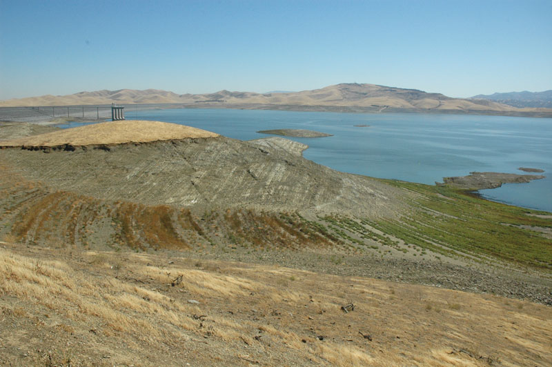
San Luis reservoir, California.
1.05
Reservoir routing uses mathematical relations to calculate
outflow from a reservoir once inflow, initial conditions,
reservoir characteristics, and operational rules are known.
1.06
The classical approach to reservoir routing is based on the storage concept.
1.07
Reservoir routing techniques based on the storage concept are referred to as
hydrologic reservoir routing methods, or storage routing methods,
to distinguish them from hydraulic routing methods.
1.08
Hydraulic routing methods use the principles or mass and momentum conservation
to obtain detailed solutions for discharges and stages throughout the reservoir.
1.09
In practice, most applications of reservoir routing have used the storage concept.
1.10
Reservoirs can be of widely differing sizes; they can range from small detention
ponds designed to diffuse flood flows from developed urban sites, to very large
reservoirs occupying substantial segments of large rivers.
1.11
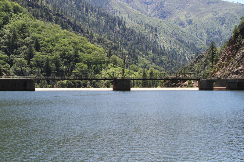
Rock Creek Dam and Reservoir, North Fork Feather River, California.
1.12
For a single reservoir, inflow is dependent on the natural upstream flows.
1.13
Outflow, however, may be either (1) uncontrolled, (2) controlled, or
(3) a combination of controlled and uncontrolled.
1.14
Uncontrolled outflow is not subject to operator intervention, for example, outflow
through an ungated spillway.
1.15
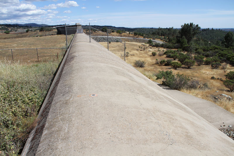
Emergency spillway at Oroville dam, California.
1.16
Controlled outflow is subject to operator intervention; for example, outflow
through a gated spillway.
1.17
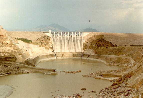
Spillway at Tarbela dam, Indus Basin Project, Pakistan.
1.18
Detention ponds and small flood-retention reservoirs are typical examples
of reservoirs with uncontrolled outflow.
1.19
In these case, an ungated spillway, or a gated spillway that is kept fully open
during the flood season, serves as outflow structure.
1.20
Therefore, outflow from the reservoir is solely a function of reservoir stage.
1.21
There are two types of reservoirs with uncontrolled outflow: (1) simulated, and (2) actual.
1.22
Simulated reservoir routing uses mathematical relations
to mimic natural diffusion processes existing in nature.
1.23
An example of simulated reservoir routing is the linear reservoir method, which is extensively
used in catchment routing.
1.24
Actual reservoir routing refers to the routing through a planned or existing reservoir,
either for design or operational purposes.
1.25
In this case, the outflow characteristics are determined by the geometric features
of the reservoir and the hydraulic properties of the outflow structure.
1.26
The most widely used method of actual reservoir routing with uncontrolled outflow is the
storage indication method.
1.27
In a reservoir with controlled outflow, gates are used to regulate flow through
the structure.
1.28
The gates are operated following established rules.
1.29
These rules determine the relation between inflow, outflow, and storage,
taking into account the daily, monthly, or seasonal downstream water demands.
1.30
Most large reservoirs operate with controlled outflow conditions.
1.31
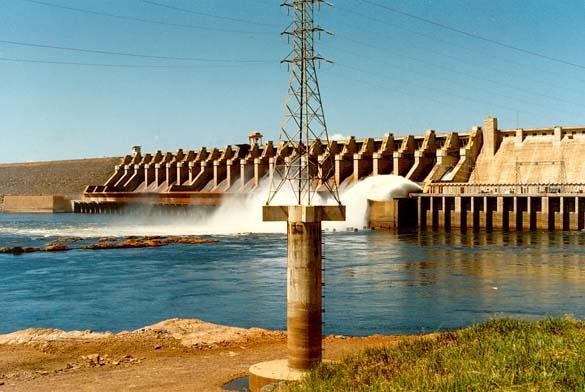
Main gated spillway, Tucurui reservoir, Para, Brazil.
1.32
In certain cases, outflow may be a combination of controlled and uncontrolled
modes, for instance, when the reservoir features a combined regulated outflow
and emergency spillway that operates only above a certain pool level.
1.33
Flow through an emergency spillway is usually of the uncontrolled type, outflow
being governed solely by the hydraulic properties of the spillway,
without the need for operator intervention.
1.34
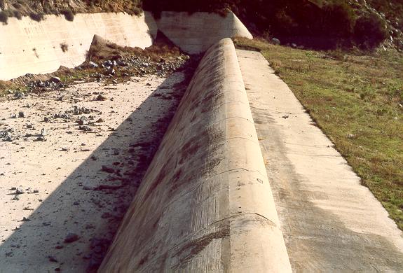
Emergency spillway at El Capitan dam, San Diego, California.
1.35
A rubber gated overflow spillway serves the purpose of choosing to control or not to control
the flow level in a reservoir during flood stages.
1.36
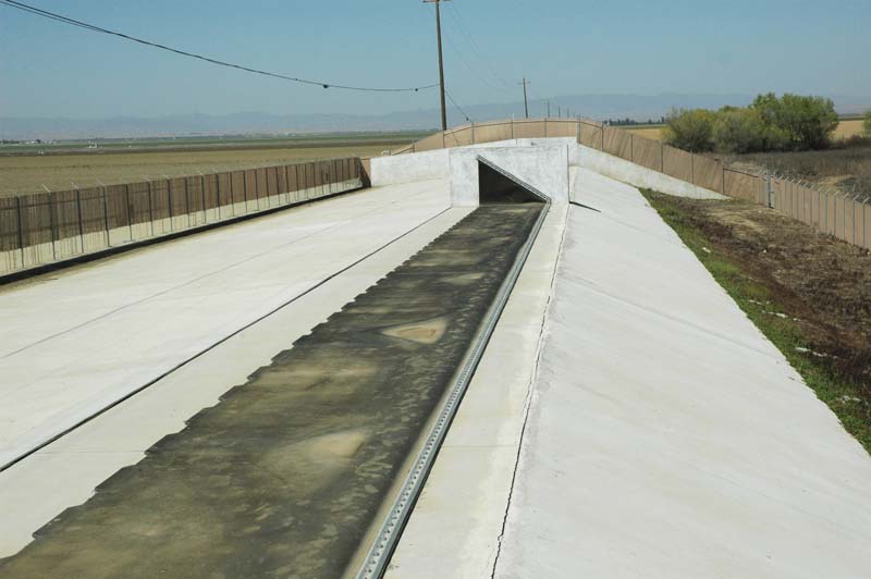
Rubber-gated spillway, Arroyo Pasajero reservoir, near Coalinga, California.
1.37
A diversion dam may feature a fuse spillway, designed to fail under extreme conditions,
reducing the risk of failure of the intake structure.
1.38
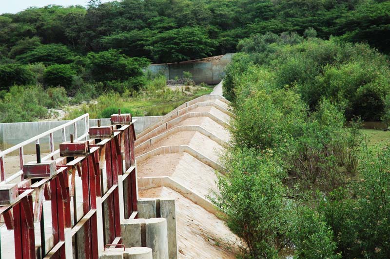
Spillway fuse, La Leche river, Lambayeque, Peru.
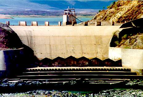
1.39
Oros dam and spillway, Ceara, Brazil.
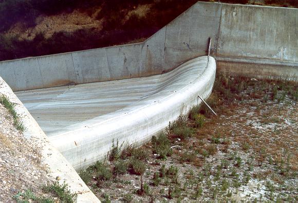
1.40
Emergency spillway, Turner reservoir, San Diego County, California.
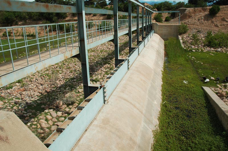
1.41
Emergency spillway, Tinajones reservoir, Lambayeque, Peru.
2. STORAGE ROUTING
2.01
The storage concept is well established in flow-routing theory and practice.
2.02
The techniques for storage routing are based on the partial differential equation
of storage.
2.03
This equation is founded on the principle of mass conservation, which states
that the change in flow per unit length in a control volume
is balanced by the change in flow area per unit time.
2.04
In partial differential equation form:
2.05
2.06
in which Q = flow rate, A = flow area, x = space, or length, and t = time.
2.07
In practice, this equation is referred to as the water continuity equation.
2.08
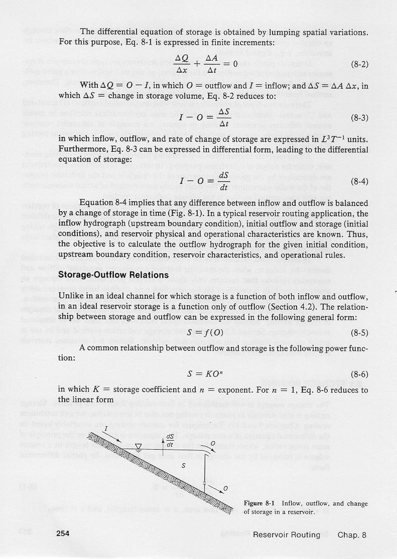
The differential equation of storage is obtained by lumping spatial variations.
2.09
For this purpose, the water continuity equation is expressed in finite increments:
2.10
2.11
With
2.12
2.13
in which O = outflow, and I = inflow, and
2.14
2.15
in which ΔS is the change in storage volume, this equation reduces to:
2.16
2.17
in which inflow, outflow, and rate of change of storage are expressed in
discharge units,
that is, L3/T.
2.18
This equation can be expressed in total differential form:
2.19
2.20
Thus, the difference between inflow and outflow is balanced by the
change of storage in time.
2.21
In a typical reservoir routing application, the inflow hydrograph, initial outflow and storage,
and reservoir physical and operational characteristics are known.
2.22
Thus, the objective is to calculate the outflow hydrograph for the given
initial condition, upstream boundary condition, reservoir characteristics, and operational
rules.
2.23
3. STORAGE-OUTFLOW RELATIONS
3.01
Unlike an ideal channel, in which storage is a function of both inflow
and outflow,
in an ideal reservoir, storage is a function only of outflow.
3.02
The relationship between storage and outflow can be expressed in the following general form:
3.03
3.04
A common relationship between outflow and storage is the following power function:
3.05
3.06
in which K = storage coefficient, and n = exponent.
3.07
For n = 1, this equation reduces to the linear form:
3.08
3.09
in which K is a proportionality constant or linear storage coefficient,
which has the units of time.
3.10
Real reservoirs usually have a nonlinear storage-outflow relationship.
3.11
Exceptions are the cases where the storage-outflow relation is indeed linear,
as in the case of the proportional weir.
3.12
The proportional weir is used in connection with
the measurements of small flows.
3.13
Simulated reservoirs are usually of the linear type.
3.14
Several linear reservoirs in series lead to cascade of linear reservoirs,
a mathematical procedure which is useful in catchment routing.
3.15
For linear reservoirs, the constant K is the storage coefficient.
3.16
Increasing the value of K increases the amount of storage simulated
by the system.
3.17
In other words, greater K values result in increased outflow hydrograph diffusion.
3.18
For routing in actual reservoirs, the nonlinear properties of the storage-outflow
relation must be determined in advance.
3.19
Outflow from an actual reservoir will depend on whether the flow
is discharged through either closed conduits, overflow spillways,
or a combination of the two.
3.20
For a free-outlet closed conduit, the ouflow formula is:
3.21
3.22
in which Q = outflow, Cd = discharge coefficient, A = flow area, and H = hydraulic head above the outlet elevation.
3.23
In SI units, the theoretical discharge coefficient is
4.43; in U.S. Customary units it is 8.02.
3.24
In practice, these values are reduced by about 30% to account
for flow contraction, and entrance and friction losses.
3.25
For an ungated overflow spillway, the formula is:
3.26
3.27
in which L = length of spillway crest, and H = hydraulic head above spillway crest.
3.28
In SI units, the theoretical discharge coefficient is 1.70, in U.S. Customary units, it is 3.09.
3.29
The discharge coefficient of an overflow spillway
varies with the shape of the spillway crest.
3.30
Lengths of spillways vary widely. Perhaps the longest spillway in the world
is that of the Boeraserie Conservancy, in Guyana, which is 8000 ft long, that is, 1515 meters.
3.31
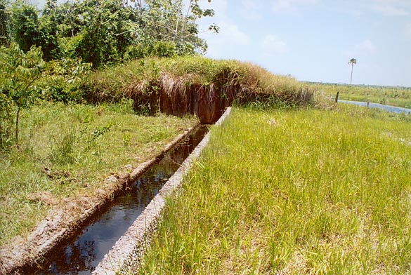
Emergency spillway, Boeraserie Conservancy, Region 1, Guyana.
3.32
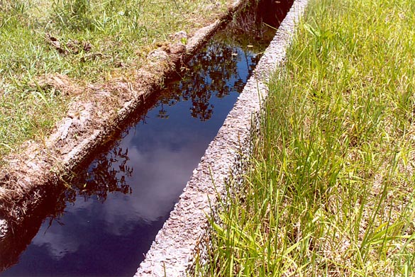
Spillway, Boeraserie Conservancy, Region 1, Guyana.
3.33
Also, for a given spillway, the discharge coefficient
is not constant, varying with hydraulic head.
3.34
Ogee-type spillways have discharge coefficients exceeding the theoretical
value, while broad-crested weirs have discharge coefficients less than the
theoretical value.
3.35
Values varying between 95% and 130% of the theoretical value have been reported.
3.36
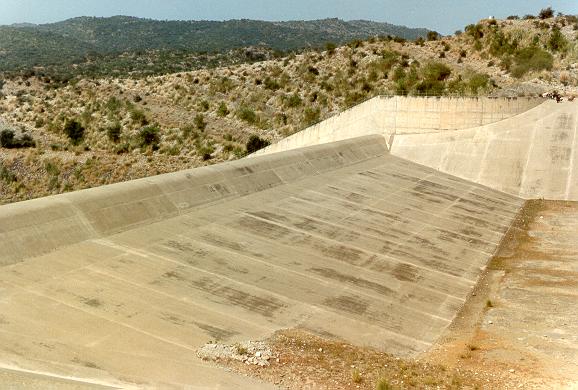
Emergency spillway, Mangla dam, Indus Basin project, Pakistan.
3.37
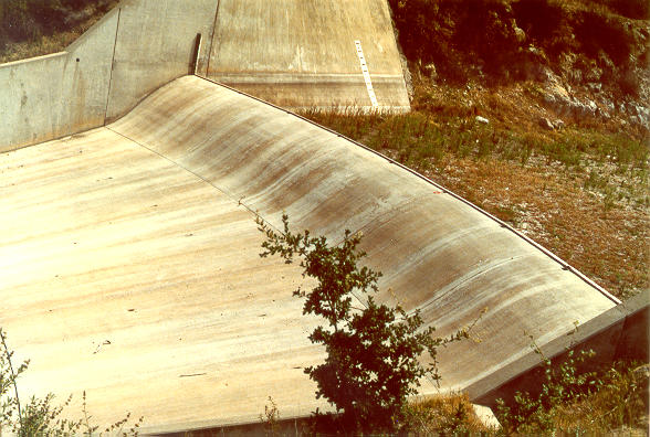
Emergency spillway, Turner reservoir, San Diego County, California.
3.38
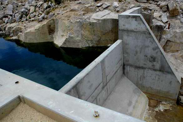
Spillway, Valle Grande dam, Cuajone, Moquegua, Peru.
3.39
In the proportional weir, the cross-sectional flow area
grows in proportion to the half-power of the hydraulic head.
3.40
Therefore, outflow is linearly related to hydraulic head, and a linear
storage-outflow relation is applicable.
Narrator: Victor M. Ponce
Music: Fernando Oñate
Editor: Flor Pérez
Copyright © 2011
Visualab Productions
All rights reserved
| 


