|
ENGINEERING HYDROLOGY: CHAPTER 082 - LINEAR RESERVOIR ROUTING
1.01 1.02
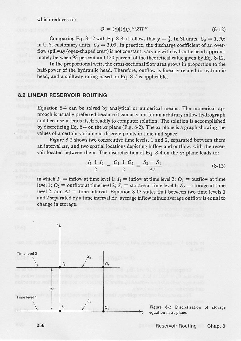
1.03 This equation can be solved by analytical or numerical means. 1.04 The numerical approach is preferred because it can account for an arbitrary inflow hydrograph and because it lends itself readily to computer solution. 1.05 The solution is accomplished by discretizing the differential equation of storage on the x-t plane. 1.06 The x-t plane is a graph showing the values of a certain variable in discrete points in time and space. 1.07 This figure shows two consecutive time levels, 1 and 2, separated between them an interval Δt, and two spatial locations depicting inflow and outflow, with the reservoir located between them. 1.08 1.09 The discretization on the x-t plane leads to: 1.10
1.11 in which I1 = inflow at time level 1, I2 = inflow at time level 2, O1 = outflow at time level 1, O2 = outflow at time level 2, S1 = storage at time level 1, S2 = storage at time level 2. 1.12 This equation states that the average inflow minus average outflow is equal to the change in storage.
2.01 For a linear reservoir, the relationship between storage and outflow is: 2.02
2.03 Therefore, at time levels 1 and 2: 2.04
2.05
2.06 in which K = storage constant. 2.07 Substituting these equations into the discretized equation of storage, and solving for outflow at time level 2: 2.08
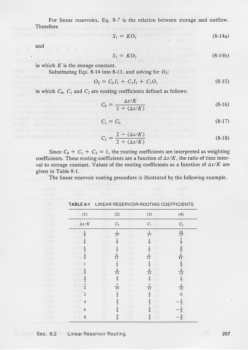
2.09 in which C0, C1, and C2 are reservoir routing coefficients defined as follows: 2.10
2.11
2.12
2.13 Since the sum of the routing coefficients is 1, the routing coefficients are interpreted as weighing coefficients. 2.14 The routing coefficients are a function only of Δt/K, the ratio of time interval to storage constant. 2.15 This ratio is dimensionless. 2.16 Values of the routing coefficients as a function of the ratio Δt/K are shown in this table. 2.17
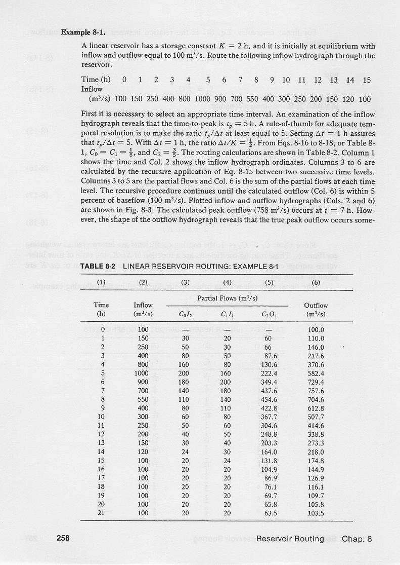
3.01 An example of linear reservoir routing is shown in this table. 3.02 For this example, we choose Δt = 1 hr, and K = 2 hr; therefore, Δt/K = 0.5. 3.03 The calculated routing coefficients are: C0 = 0.2, C1 = 0.2, C2 = 0.6. 3.04 It is confirmed that the sum of routing coefficients is equal to 1. 3.05 Column 1 shows the time in hours. 3.06 Column 2 shows the inflow hydrograph, that is, the upstream boundary condition. 3.07 Columns 3 to 5 show the weighted flows. 3.08 For instance, in Column 3, Line 2: 3.09
3.10 Likewise, in Column 4, Line 2: 3.11
3.12 And, in Column 5, Line 2: 3.13
3.14 Column 6 is the routed outflow, obtained by summing Columns 3, 4 and 5 across, as shown here for Line 2. 3.15
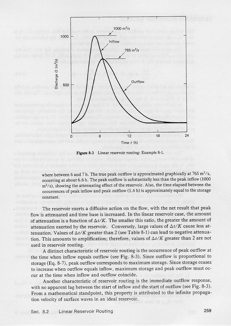
3.16 For this example, the peak inflow, 1000 m3/s, shown in Column 2, Line 5, occurs at time equal to 5 hr. 3.17 The calculated peak outflow, 757.6 m3/s, shown in Column 6, Line 7, occurs at time equal to 7 hr. 3.18 This figure shows the plotted inflow and outflow hydrographs for the given example. 3.19 The true peak outflow occurs somewhere between 6 and 7 hr. 3.20 The true peak outflow is approximated graphically at 756 m3/s, occurring at about 6.6 hr. 3.21
3.22
4. ROUTING ANALYSIS 4.01 The reservoir exerts a diffusive action of the flow, with the net result that peak flow is attenuated and time base increased. 4.02 The amount of attenuation is a function of the ratio Δt/K. 4.03 The smaller this ratio, the greater the amount of attenuation exerted by the reservoir. 4.04 Conversely, large values of the Δt/K cause less attenuation, that is, less diffusion. 4.05 Values of Δt/K greater than 2 lead to a negative routing coefficient C2, and consequently, to negative diffusion. 4.06 This amounts to amplification; therefore, values of Δt/K greater than 2 are not used in reservoir routing. 4.07 A distinct characteristic of reservoir routing is the occurrence of peak outflow precisely at the time when inflow equals outflow. 4.08 By definition, outflow is proportional to storage. 4.09 Therefore, peak outflow corresponds to peak, or maximum, storage. 4.10 Since storage ceases to increase when outflow equals inflow, it follows that peak storage and peak outflow must occur at the time when inflow and outflow coincide. 4.11 Another characteristic of reservoir routing is the immediate outflow response, with no apparent lag between the start of inflow and the start of outflow. 4.12 From a mathematical standpoint, this property is attributed to the infinite propagation velocity of surface waves in an ideal reservoir. 4.13 In practice, when the water surface slope approaches zero, as in a typical reservoir, the propagation velocity of short, energy-transporting waves approaches infinity.
Narrator: Victor M. Ponce Music: Fernando Oñate Editor: Flor Pérez
Copyright © 2011 Visualab Productions All rights reserved
|


