|
ENGINEERING HYDROLOGY: CHAPTER 083 - STORAGE INDICATION METHOD
1. STORAGE INDICATION
1.01
The storage-indication method is used to route
streamflows through actual reservoirs, for which the relationship between outflow and storage
is usually of a nonlinear nature.
1.02
The differential equation of storage is:
1.03
1.04
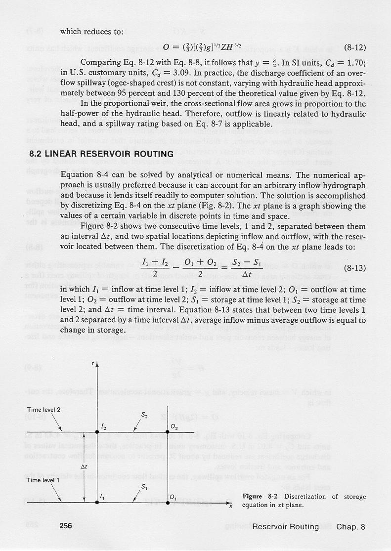
This equation is discretized on the x-t plane to yield:
1.05
I1 + I2 O1 + O2 S2 - S1
2 2 Δt
|
1.06
This equation is transformed into its equivalent form:
1.07
1.08
in which the unknown values S2 and O2 appear on the left side of the equation,
and the known values appear on the right side.
1.09
The left-hand side of this equation is referred to as the storage indication quantity, at time level equal 2.
1.10
1.11
2. METHODOLOGY
2.01
In the storage indication method, it is first necessary to assemble topographic
and hydraulic reservoir
data in suitable form.
2.02
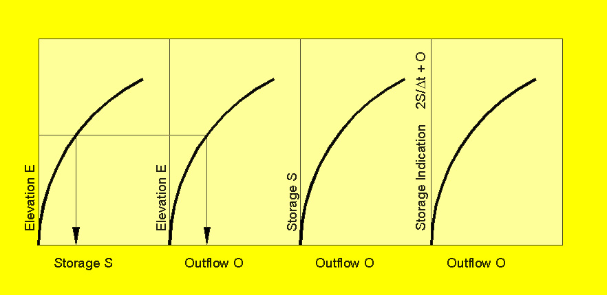
For this purpose, the following tables are prepared:
2.03
1. Elevation-Storage
2.04
2. Elevation-Outflow
2.05
3. Storage-Outflow
2.06
4. Storage Indication-Outflow
2.07
2.08
For computer applications, these curves are replaced by tables of corresponding elevation-storage-outflow-storage indication
quantities.
2.09
The elevation-storage relation is determined based on topographic information.
2.10
The minimum elevation is that for which storage is zero, and the maximum elevation is the
elevation of the dam crest.
2.11
The elevation-outflow relation is based on the hydraulic properties of the outlet works,
either closed conduit, overflow spillway or a combination of the two.
2.12
In the typical application, the reservoir pool elevation provides a head over the outlet elevation
or spillway crest,
and the outflow is calculated using hydraulic formulas.
2.13
When routing flows through emergency spillways, storage is alternatively expressed in terms
of surcharge storage, that is, the storage above a certain level, usually the emergency spillway
crest elevation.
2.14
Elevation-storage and corresponding elevation-outflow data lead to the storage-outflow relation.
2.15
In turn, the storage-outflow relation leads to the storage indication-outflow
relation.
2.16
The storage-indication quantity is:
2.17
2.18
with S = storage, O = outflow, and Δt = time interval.
2.19
To develop a storage indication-outflow relation, it is first necessary to select a time interval such
that the resulting linearization of the inflow hydrograph remains a close approximation
of the actual nonlinear shape of the hydrograph.
2.20
For smoothly rising hydrographs, a minimum value of tp/Δt = 5 is recommended,
in which tp is the time to peak of the inflow hydrograph.
2.21
In practice, a computer-aided calculation would normally used a much greater ratio,
say 10 to 20.
2.22
Given Δt and a set of corresponding storage S and outflow O values, the storage indication quantity can be calculated
and plotted against outflow.
2.23
Once the data has been prepared, the storage indication equation is used in a recursive mode
to calculate the outflow hydrograph.
2.24
2Sn+1 2Sn
|
+
| On+1 = In + In+1 +
|
| - On |
Δt Δt
|
2.25
The following steps are required:
2.26
1. Set the counter at n = 1
2.27
2. Use the storage-indication equation to calculate the storage indication quantity
at time level n+1
2.28
2.29
3. Use the storage indication quantity versus outflow relation to determine the outflow
at time level n+1
2.30
4. Use the storage-indication quantity and outflow at time level n+1 to calculate
2.31
2Sn+1 2Sn+1
|
-
| On+1 = [
|
| + On+1 ]
- 2 (On+1) |
Δt Δt
|
2.32
5. Increment the counter by 1, go back to step 2, and repeat.
2.33
The recursive procedure is terminated either when the inflow ceases or when the outflow
hydrograph has substantially receded back to baseflow discharge.
3. EXAMPLE 1
3.01
The procedure is illustrated by the following example.
3.02
Assume a linear reservoir with a storage constant K = 2 hr.
3.03
Therefore, the outflow-storage relation is:
3.04
3.05
in which O is in m3/s and storage is in (m3/s)-hr for computational convenience.
3.06
Selecting Δt = 1 hr, the storage-indication variable is:
3.07
3.08
From which the outflow-storage indication relation is:
3.09
3.10
In other words, for this example, outflow is 1/5 of storage indication.
3.11
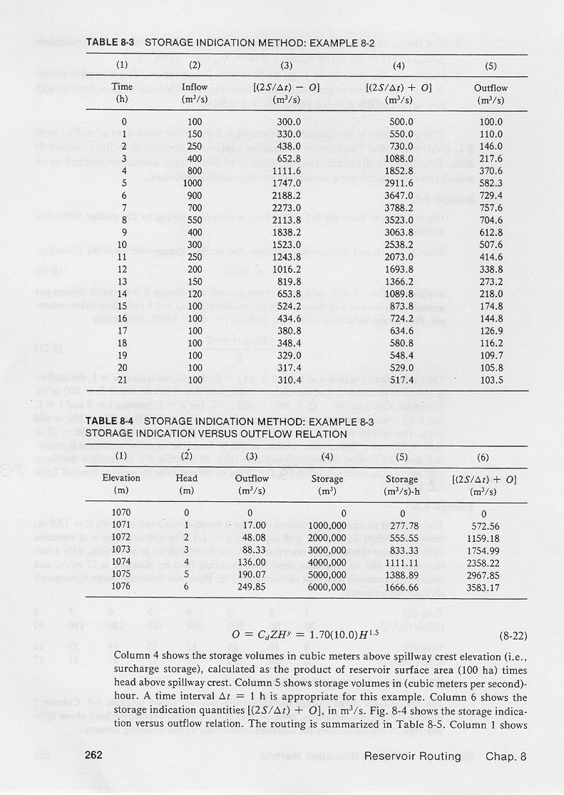
The calculations are shown in this table.
3.12
Column 1 shows the time in hours.
3.13
Column 2 shows the inflow hydrograph ordinates.
3.14
Column 3 shows the related variable
3.15
3.16
Column 4 shows the storage indication variable.
3.17
3.18
Column 5 shows the routed outflow hydrograph.
3.19
For time t = 0, the initial condition is that outflow is assumed to be equal to the inflow.
3.20
Thus, for time t = 0,
the outflow in Column 5 is equal to the inflow in Column 2, that is 100 m3/s.
3.21
Therefore, for time t = 0,
the storage-indication quantity in Column 4 is equal to 5 times the outflow 100,
that is, 500.
3.22
For time t = 0, the variable in Column 3 is equal to Column 4 minus twice the value of
Column 5, that is:
3.23
3.24
Next, for time t = 1, the storage indication quantity in Column 4 is equal to
the inflow at t = 0, plus the inflow at t = 1, plus the value of Column 3 at t = 0, that is:
550.
3.25
3.26
Next, for t = 1, the outflow in Column 5 is 1/5 of the value of Column 4, 550, that is 110.
3.27
The recursive procedure continues until the outflow has substantially receded to baseflow, as shown in Column 5, line 21.
3.28
The storage-indication method is applicable to reservoir routing in planned or existing reservoirs, for which
the storage-outflow relation is typically of a nonlinear nature.
3.28
Narrator: Victor M. Ponce
Music: Fernando Oñate
Editor: Flor Pérez
Copyright © 2011
Visualab Productions
All rights reserved
| 


