|
ENGINEERING HYDROLOGY: CHAPTER 092 - KINEMATIC WAVES
1. KINEMATIC WAVE EQUATION
1.01
Three types of unsteady open-channel flow waves are commonly used
in engineering hydrology: (1) kinematic, (2) diffusion, and (3) dynamic.
1.02
Kinematic waves are the simplest type of wave, and dynamic waves are the
most complex.
1.03
Diffusion waves lie somewhere in between kinematic and dynamic waves.
1.04
The kinematic wave equation is based on the
principle of mass conservation within a control volume.
1.05
This principle states that the difference between outflow and inflow within
one time interval is balanced by
a corresponding change in volume.
1.06
In terms of finite differences:
1.07
| (Q2 - Q1) Δt +
(A2 - A1) Δx = 0 |
|
1.08
in which Q = flow, A = flow area, Δt = time interval, and Δx =
space interval.
1.09
In differential form, this equation can be written as follows:
1.10
1.11
This is the equation of conservation of mass, or equation of
continuity.
1.12
The equation of conservation of momentum contains
(1) local inertia, (2) convective inertia, (3) pressure, or flow depth gradient,
(4) friction, (5) gravity, and (6) momentum source term.
1.13
In the kinematic wave equation, a statement of uniform flow is used
in lieu of the conservation of momentum.
1.14
Uniform flow is strictly a balance of gravity and friction.
1.15
Therefore, the rest of the terms, including pressure gradient, inertia,
and momentum source are excluded from the formulation.
1.16
In other words, a kinematic wave is a simplified wave that does not include
these terms of processes.
1.17
This simplification imposes certain limits on the applicability
of the kinematic wave.
1.18
Uniform flow in open channels is described by the Manning or Chezy formulas.
1.19
The Manning equation is:
1.20
1.21
in which R = hydraulic radius, in meters, Sf = friction slope,
in meters per meter, and n = Manning friction coefficient.
1.22
The hydraulic radius is:
1.23
1.24
in which P = wetted perimeter.
1.25
Substituting the hydraulic radius into the Manning equation leads to:
1.26
1.27
Assume for simplicity that n, Sf and P are constant.
1.28
This is the case of a hydraulically wide channel, where the wetted perimeter
may be assumed to be independent
of flow area.
1.29
Assuming a rating equation of the following type:
1.30
1.31
It follows that α is:
1.32
1.33
and β is:
1.34
1.35
Differentiating the rating equation with respect to flow area leads to the wave
celerity:
1.36
1.37
in which V = mean flow velocity.
1.38
Multiplying the continuity equation with the wave celerity, and applying
the chain rule of differentiation, leads to the kinematic
wave equation:
1.39
1.40
Or, alternatively:
1.41
1.42
These equations describe the movement of waves that are kinematic
in nature.
1.43
These are referred to as kinematic waves, that is, waves for which
inertia and the flow depth gradient have been neglected.
1.44
The kinematic wave equation is a first-order partial differential
equation.
1.45
Therefore, kinematic waves travel with celerity dQ/dA and do not attenuate.
1.46
Wave attenuation, that is wave diffusion,
can be described only by a second-order partial differential equation.
1.47
The absence of attenuation in a kinematic wave can be further explained
by the following mathematical argument.
1.48
Since dQ/dA is the celerity of the unsteady wavelike features of the flow,
it can be replaced by dx/dt:
1.49
1.50
Therefore:
1.51
1.52
which is a statement of the total derivative dQ/dt.
1.53
1.54
Since the right-hand side of this equation is zero, it follows that dQ/dt = 0, that is, discharge Q remains
constant in time for waves traveling with celerity dQ/dA.
1.55
This is interpreted as the lack of diffusion of a kinematic wave.
1.56
The kinematic wave equation is a nonlinear first-order partial differential equation
describing the change of discharge in time and space.
1.57
Its is nonlinear because the wave celerity varies with discharge.
1.58
However, the nonlinearity is usually small, and therefore, the kinematic wave
equation can be solved in a linear mode by considering the wave celerity
to be constant.
1.59
The solution of the kinematic wave can be accomplished by analytical or numerical means.
1.60
The simplest kinematic wave solution is a linear numerical solution.
2. NUMERICAL SCHEMES
2.01
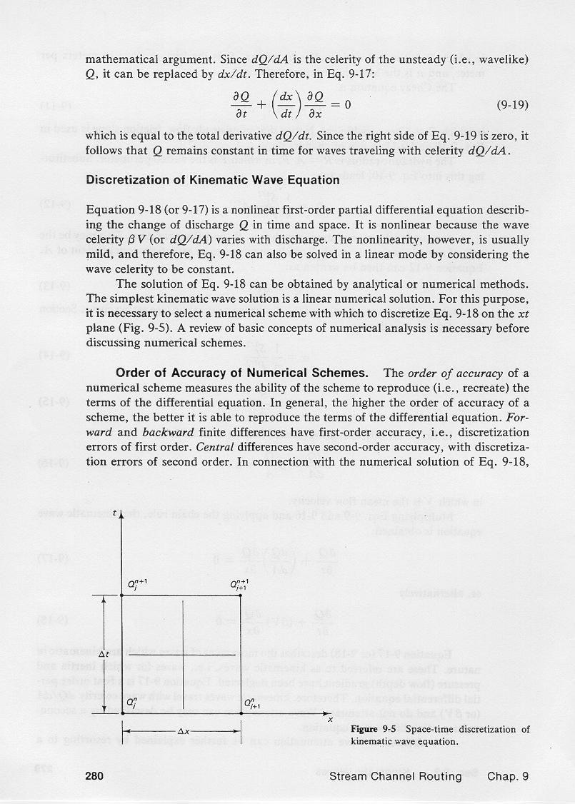
Numerical schemes are discrete formulations, on the x-t plane,
of the governing differential equations.
2.02
The order of accuracy of a numerical scheme measures the ability of the scheme
to reproduce the terms of the differential equation.
2.03
In general, the higher the order of accuracy of the scheme, the better it is able to
reproduce the terms of the differential equation.
2.04
Forward and backward finite differences have first-order accuracy, that is, discretization
errors of first order.
2.05
Central differences have second order accuracy, with discretization errors of second order.
2.06
The numerical solution of the kinematic wave equation with first-order schemes creates numerical
diffusion and dispersion, while second order schemes create only numerical dispersion.
2.07
Numerical diffusion is caused by first-order discretization errors;
numerical dispersion by second-order errors.
2.08
A third-order scheme of the kinematic wave equation provides the exact solution,
creating neither numerical diffusion nor dispersion.
2.09
Numerical diffusion and/or dispersion are caused by the finite size of the grid and not necessarily related to
the physical problem.
3. SECOND-ORDER SCHEME
3.01
The discretization of the kinematic wave equation
with a linear, second-order accurate scheme,
using central differences in time and space, leads to the following routing equation:
3.02
n+1 n+1 n n
| Qj+1 = C0 Qj
+ C1 Qj + C2 Qj+1 |
|
3.03
in which the routing coefficients are:
3.04
3.05
3.06
and C is the Courant number, defined as follows:
3.07
3.08
Note that the Courant number is the ratio of physical wave celerity βV to
grid celerity Δx/Δt.
3.09
The Courant number is a fundamental concept in the numerical solution of hyperbolic
partial differential equations such as the kinematic wave equation.
3.10
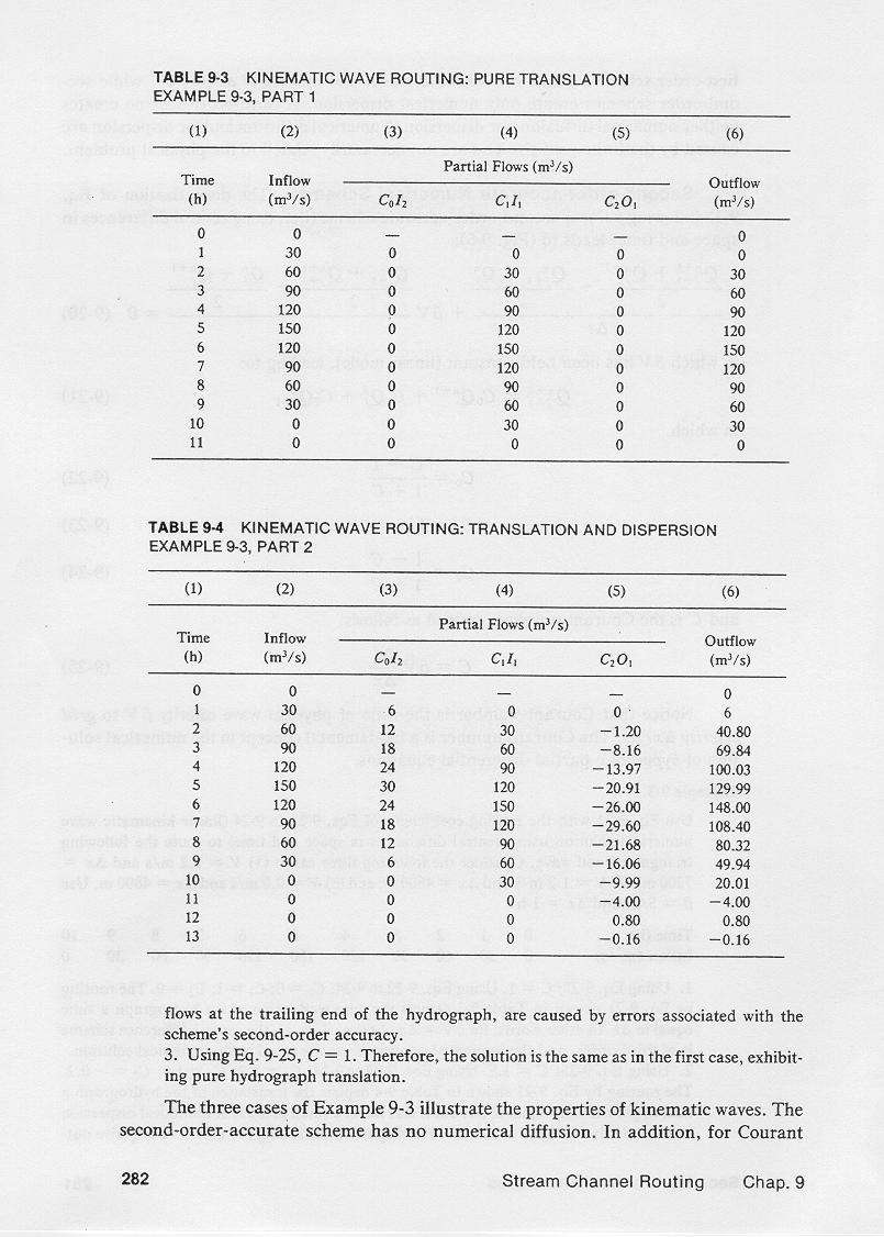
This table shows the kinematic wave routing of an inflow hydrograph, with wave celerity and space and time
intervals such that the Courant number C = 1.
3.11
The table shows the exact translation of the hydrograph, reproducing the exact
solution of the kinematic wave.
3.12
This other table shows the kinematic wave routing of an inflow hydrograph, with wave celerity and space and time
intervals such that the Courant number C = 1.5.
3.13
In this case, the outflow hydrograph is diffused to a peak of 148 m3/s, as compared to an inflow of
150 m3/s.
3.13
Also, the outflow hydrograph is dispersed, with unrealistic negative outflows present
at the tail of the hydrograph.
3.14
We conclude that the second-order accurate numerical solution of the kinematic
linear wave equation is impractical, because it only works well for the trivial case of Courant number C = 1.
4. FIRST-ORDER SCHEME
4.01
The discretization of the kinematic wave equation
with a linear, first-order accurate scheme,
using backward differences in both time and space, leads to the following routing equation:
4.02
4.03
in which the routing coefficients are:
4.04
4.05
4.06
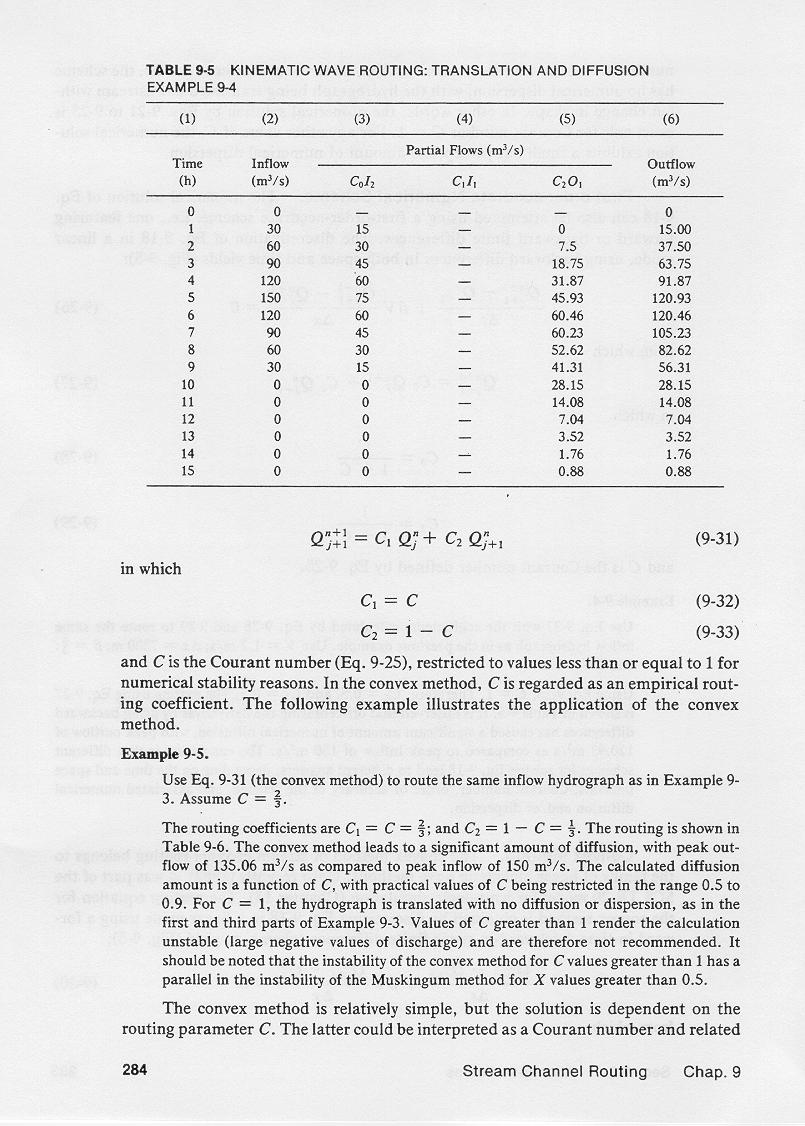
This table shows the kinematic wave routing of an inflow hydrograph, with wave celerity and space and time
intervals such that the Courant number C = 1.
4.07
The table shows that in this case, the outflow hydrograph for C = 1
is translated and diffused, with the peak outflow at 120.93 m3/s, as compared to a peak inflow of 150 m3/s.
4.08
Additionally, the time base has increased from 10 hr to more than 15 hr.
4.09
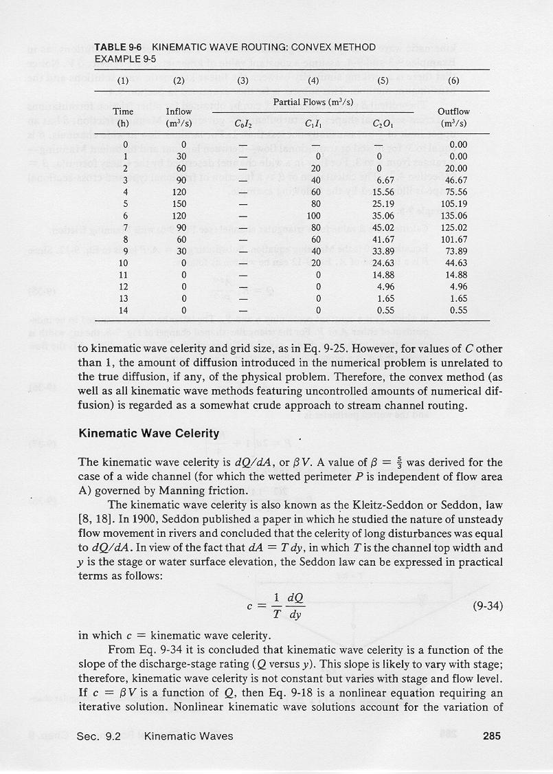
The conclusion is that different schemes for solving the kinematic wave equation
lead to different answers, depending on the amount of numerical diffusion
and dispersion.
4.10
4.11
4.12
4.13
4.14
Narrator: Victor M. Ponce
Music: Fernando Oñate
Editor: Flor Pérez
Copyright © 2011
Visualab Productions
All rights reserved
| 


