|
ENGINEERING HYDROLOGY: CHAPTER 101 - TIME-AREA METHOD
1. CATCHMENT ROUTING
1.01
Catchment routing refers to the calculation of flows in time and space
within a catchment.
1.02
The objective of catchment routing is to transform effective rainfall into
streamflow.
1.03
This can be accomplished in two ways: (1) a lumped method, and (2) a distributed
method.
1.04
The lumped methods have one or more parameters; the distributed methods can
have hundreds or more parameters.
1.05
In the lumped methods, rainfall can vary in time but not in space.
1.06
On the other hand, in the distributed methods,
rainfall can vary in time and space.
1.07
Methods for catchment routing are similar to those of reservoir and stream channel
routing.
1.08
In fact, many techniques used in reservoir and stream channel routing are also
applicable to catchment routing.
1.09
For instance, the concept of linear reservoir is used in both reservoir and catchment
routing.
1.10
Kinematic wave techniques were originally developed for river routing,
but have since been applied to catchment routing.
1.11
Methods of catchment routing are of two types: (1) hydrologic, and (2) hydraulic.
1.12
Hydrologic methods are based on the storage concept and are spatially lumped
to provide an outflow hydrograph at the catchment outlet.
1.13
Examples of hydrologic catchment routing methods are: (1) the time-area method, and
(2) the cascade of linear reservoirs.
1.14
Hydraulic routing methods use kinematic or diffusion waves to simulate
surface runoff within a catchment in a distributed context.
1.15
Unlike hydrologic routing methods,
hydraulic routing methods can provide runoff hydrographs inside the catchment.
1.16
Catchment routing methods can use (1) parametric, that is, empirical,
(2) conceptual, and/or
(3) deterministic
components.
1.17
For instance, the hydrograph obtained by the time-area method can be routed
through a linear reservoir using a storage constant derived by empirical means.
1.18
The cascade of linear reservoirs is a typical example of a conceptual model used
in catchment routing.
1.19
Kinematic and diffusion models are examples of deterministic methods
of catchment routing.
2. TRANSLATION AND STORAGE
2.01
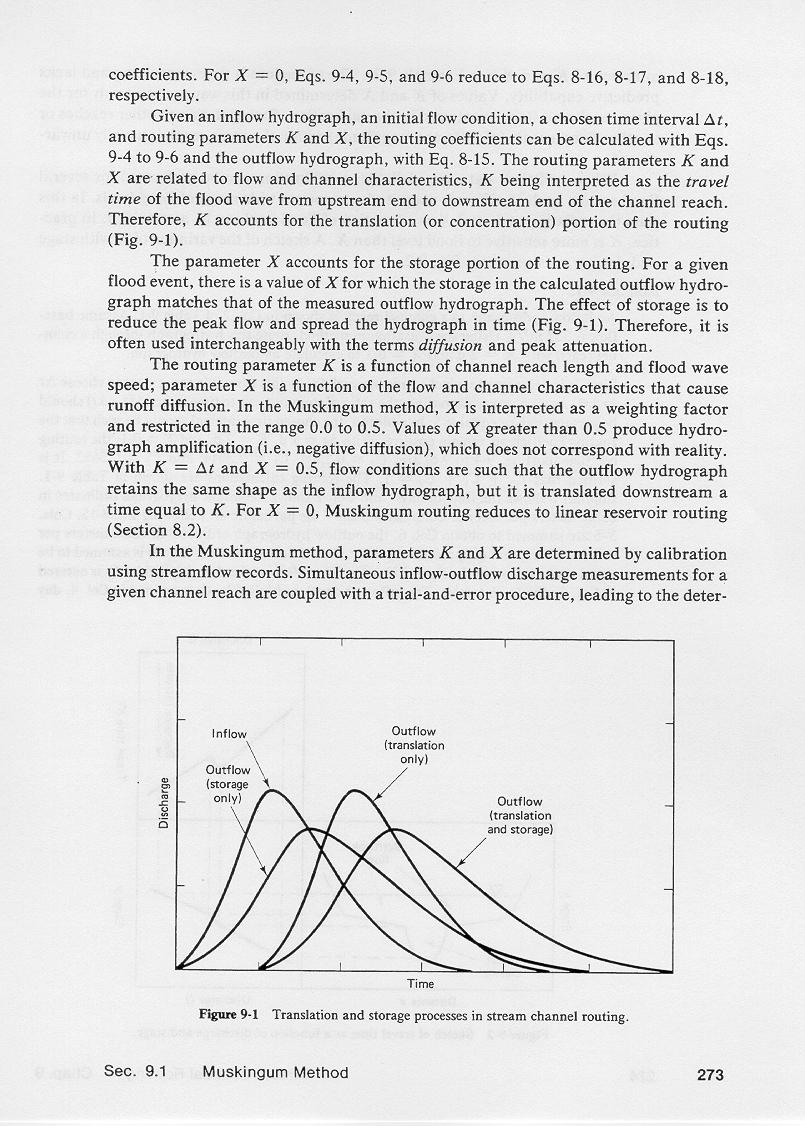
The concepts of translation and storage are central to the study
of flow routing, whether in catchment, reservoirs, or channels.
2.02
Unlike reservoir and channel routing, in catchment routing
translation and storage can be studied separately.
2.03
Translation is interpreted as the movement of water in a direction parallel
to the channel bottom.
2.04
Storage is interpreted as the movement of water in a direction
perpendicular to the channel bottom.
2.05
Translation is synonymous with runoff concentration, a first-order process.
2.06
Storage is synonymous with runoff diffusion, a second-order process.
2.07
In reservoir routing, storage is the predominant mechanism, with translation
almost nonexistent.
2.08
In fact, translation is nonexistent in
hydrologic reservoir routing.
2.09
In stream channel routing, the situation is reversed,
with translation being the predominant mechanism, with storage usually
playing only a minor role.
2.10
This is the reason why kinematic and diffusion models are useful tools in stream
channel routing.
2.11
In catchment routing, translation
and storage are about equally important.
2.12
This fact makes possible the separate calculation of translation and storage.
2.13
The translation effect is related to runoff concentration; the storage effect is
related to runoff diffusion.
3. TIME-AREA METHOD
3.01
The time-area method of hydrologic catchment routing transforms an effective storm
hyetograph into a runoff hydrograph.
3.02
The method accounts for translation only and, significantly, it
does not include storage.
3.03
Therefore, hydrographs calculated by the time-area method show a
lack of diffusion, resulting in higher peak flows that those that would
have been obtained if storage had been taken into account.
3.04
If necessary, storage can be incorporated by routing the outflow
from the time-area method through a linear reservoir.
3.05
The required amount of storage is determined by calibrating the linear reservoir
storage constant K with measured streamflow data.
3.06
Alternatively, suitable values of K can be estimated based on
regional analysis.
3.07
The time-area method is essentially an extension of the runoff concentration
principle used in the rational method.
3.08
However, unlike the rational method, the time-area method can account for the temporal
variation of rainfall intensity, that is, for a storm hyetograph.
3.09
Therefore, the applicability of the time-area method is extended to
midsize catchments.
3.10
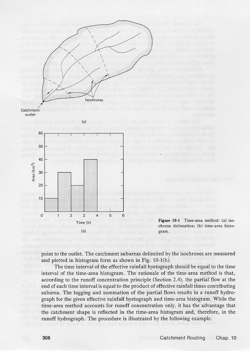
The time-area method is based on the concept of time-area histogram, that is,
a histogram of contributing subcatchment areas.
3.11
To develop a time-area histogram, the catchment's time of concentration is divided
into a number of equal intervals.
3.12
Cumulative time at the end of each interval is used to divide
the catchment into zones delimited by isochrone lines, that is,
the loci of points of equal travel time to the catchment outlet, as shown in this
figure.
3.13
For any point inside the catchment, the travel time refers to the time that it would
take a parcel of water to travel from that point to the outlet.
3.14
The catchment subareas delimited by the isochrone lines are measured and plotted in histogram
form as shown here.
3.15
The time interval of the effective rainfall hyetograph must be equal to the time
interval of the histogram of contributing drainage areas.
3.16
The rationale of the time-area method is that, according
to the runoff concentration principle, the partial flow at the end of each time interval q
is equal to the product of effective rainfall intensity i times contributing drainage
area a.
3.17
3.18
The lagging and summation of the partial flows results in a runoff hydrograph
for the given hyetograph and histogram.
3.19
Effectively, the time-area method accounts for runoff concentration only,
lacking runoff diffusion.
3.20
An advantage of the method is that the catchment shape and consequently, the
catchment response, are reflected in the time-area histogram,
and, therefore, in the runoff
hydrograph.
4. EXAMPLE
4.01
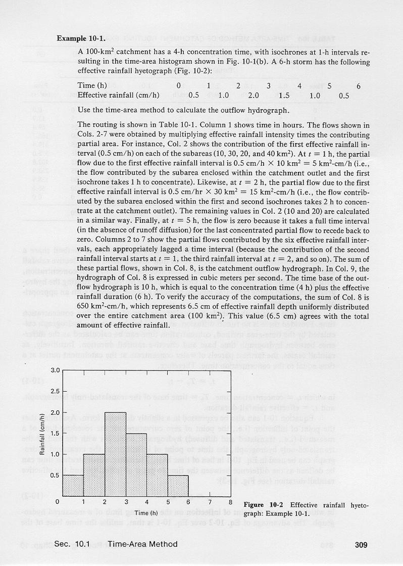
A 100 km2 catchment has a time of concentration of 4 hours, with isochrones
at 1-hr intervals resulting in the time-area histogram shown here.
4.02
A 6-hr storm has the effective rainfall hyetograph shown here...
4.03
Effective rainfall hyetograph
| Time (hr)
| 1
| 2
| 3
| 4
| 5
| 6
|
| Effective rainfall (cm/hr)
| 0.5
| 1.0
| 2.0
| 1.5
| 1.0
| 0.5
|
|
4.04
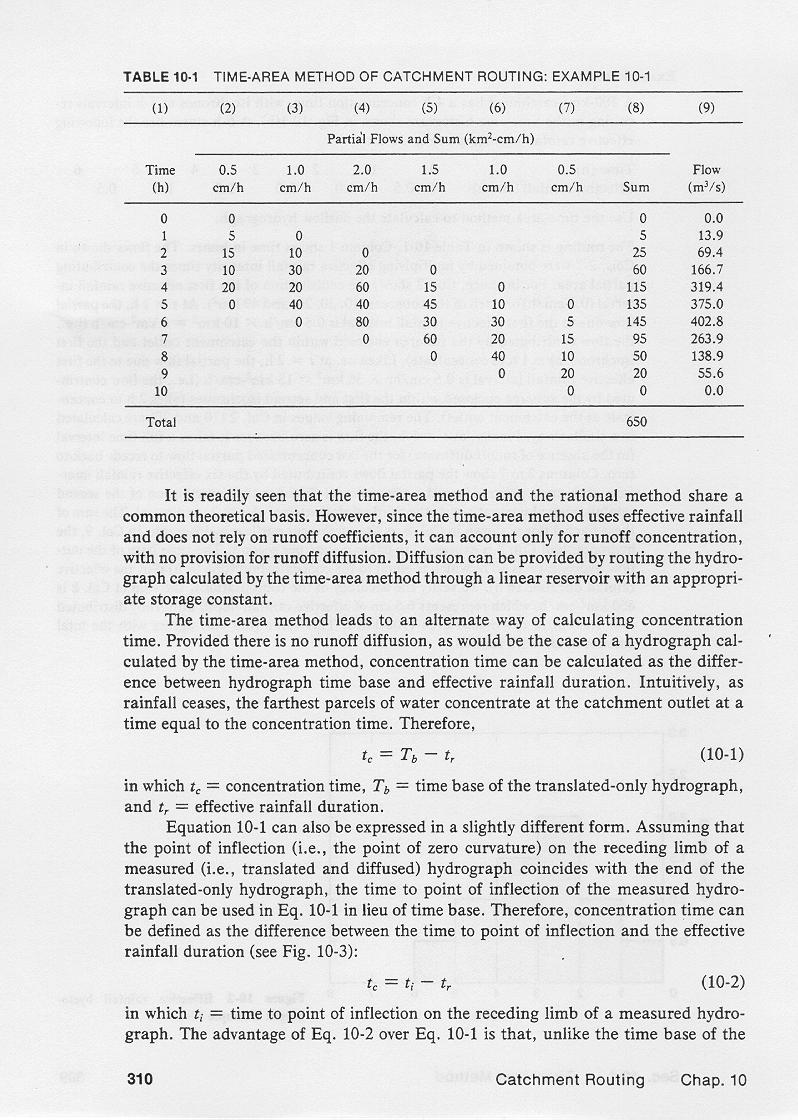
The computational procedure is shown in this table.
4.05
Column 1 shows the time in hours.
4.06
Column 2 shows the product of the first effective rainfall increment,
that is, 0.5 cm/hr,
times each of the respective histogram subareas, expressed as a partial flow hydrograph, starting
at zero at time = 0, and returning to zero at time = 5 hr.
4.07
The formula is:
4.08
4.09
Columns 3 to 7 show the ordinates of the partial flow hydrographs
for the second, third, fourth, fifth, and sixth
rainfall increments, respectively.
4.10
Column 8 shows the sum of Columns 2 to 7, across, in (km2-cm/hr) flow units.
4.11
Column 9 is Column 8 converted to units of m3/s.
4.12
Column 9 is the catchment's outflow hydrograph calculated by the time-area method.
4.13
The time base of the outflow hydrograph is 10 hr, which is equal to the time of concentration, 4 hr,
plus the rainfall duration, 6 hr.
4.14
The sum of Column 8 is 650 km2-cm/hr, which represents a total rainfall volume of 6.5 cm, in hourly increments,
uniformly distributed over the entire 100 km2 catchment.
5. ASSESSMENT
5.01
It is readily seen that the time-area method and the rational method share a common
theoretical basis.
5.02
They are both based on the runoff concentration principle.
5.03
However, since the time-area method uses effective rainfall and does
not rely on runoff coefficients, it can account only for runoff
concentration, with no provision for runoff diffusion.
5.04
Thus, the time-area method solves only the translation portion of the catchment routing
problem.
5.05
As a second step, diffusion can be provided by
routing the time-area hydrograph
through a linear reservoir, using an appropriate storage constant.
5.06
In this way, the method remains conceptual.
5.07
The time-area method leads to an alternate way of calculating time of
concentration.
5.08
Since the time-area method does not provide diffusion,
the time of concentration is effectively the difference between hydrograph time
base and rainfall duration.
5.09
Under runoff concentration only, the time of concentration is the time
elapsed between the cessation of rainfall and the cessation of runoff. Therefore:
5.10
5.11
in which tc = time of concentration, Tb = time base of the
time-area hydrograph, and tr = effective rainfall duration.
5.12
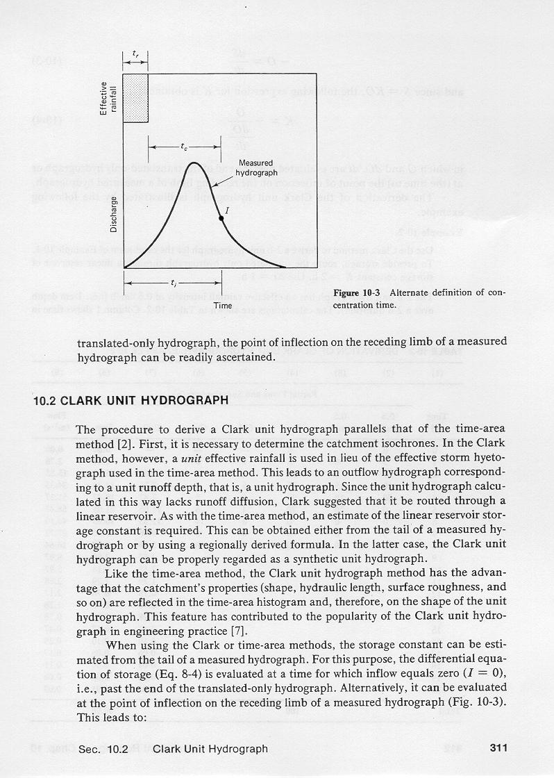
The point of inflection on the receding limb of a measured hydrograph, that is,
the point of zero curvature, is shown here.
5.13
On a measured hydrograph, which is typically
translated and diffused, the point of inflection coincides
with the end of the translated-only, or time-area hydrograph.
5.14
The time to point of inflection can be used in lieu of the time base of the
translated-only hydrograph.
5.15
Therefore, time of concentration can be expressed as the difference between
the times to point of inflection and end of rainfall, as follows:
5.16
5.17
in which ti = time to the point of inflection.
5.18
Unlike the time base of a translated-only hydrograph, the time to point of inflection
of a measured hydrograph can be readily ascertained.
5.19
5.20
5.21
5.22
5.22
Narrator: Victor M. Ponce
Music: Fernando Oñate
Editor: Flor Pérez
Copyright © 2011
Visualab Productions
All rights reserved
| 


