|
OPENCHANNEL 011: OPEN-CHANNEL FLOW
1. DEFINITION 1.01 Open-channel flow is the area of hydraulic engineering that deals with the analysis and design of open channels. 1.02 Open-channel flow differs from closed-conduit flow in that it has a free surface. 1.03 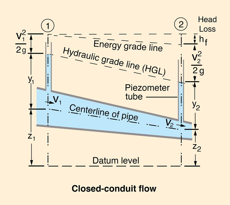
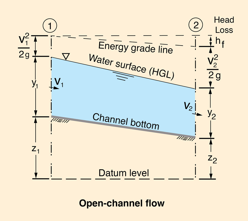
1.04 Closed-conduit flow is under pressure, while open-channel flow is not. 1.05 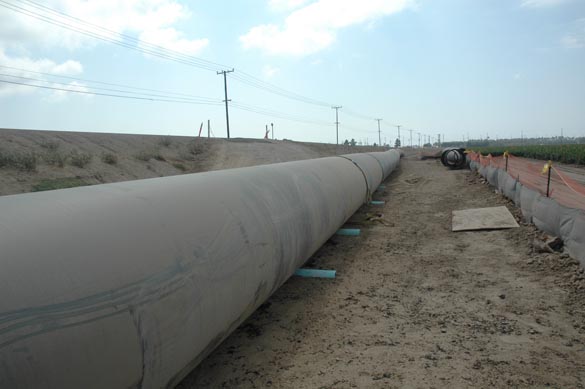
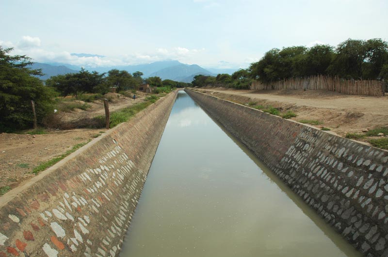
1.06 The presence of a free surface makes open-channel flow somewhat more complex that closed-conduit flow. 1.07 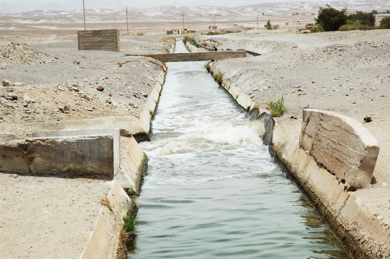
1.08 The free-surface is likely to vary in space and time. 1.09 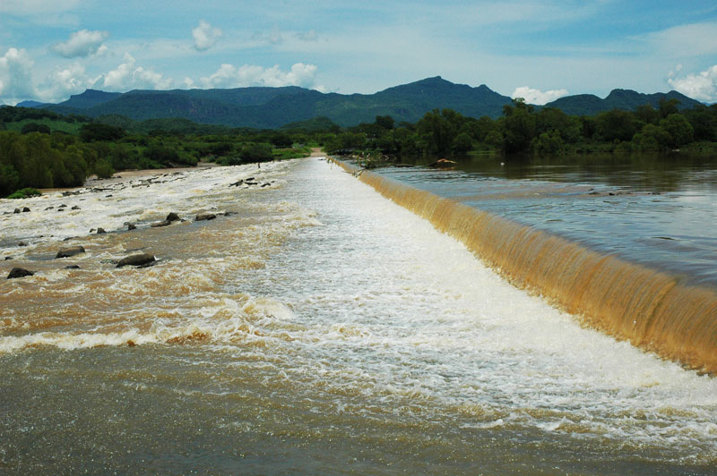
1.10 In closed-conduit flow, the cross section is fixed. 1.11 In open channels, the flow cross section is not fixed, varying with the flow. 1.12 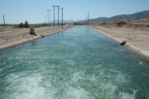 This photo shows the Wellton-Mohawk canal in Arizona, immediately downstream
of a pumping station.
1.13 In open channels, the boundary roughness varies with the nature of the material surrounding the channel, ether plastic, steel, concrete, or, in the case of unlined canals or natural streams, soils and vegetation. 1.14 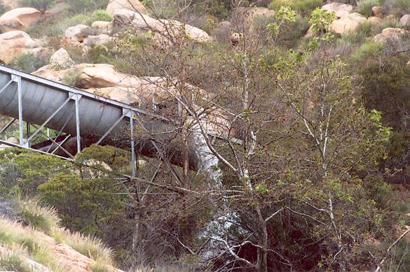 This photo shows the Dulzura conduit, in San Diego County, California, overflowing after heavy rains on March 5, 2005.
1.15 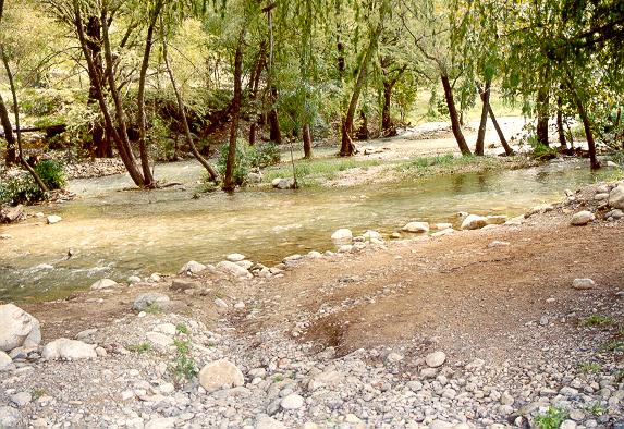
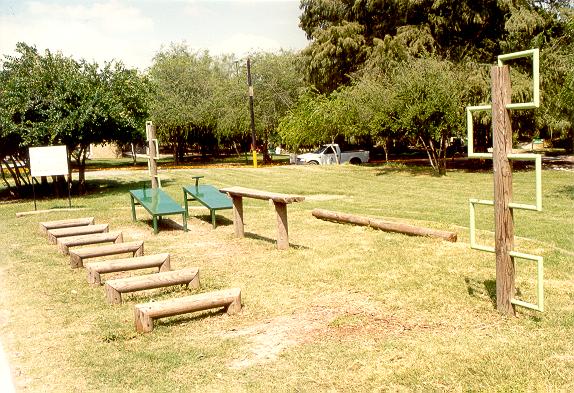 These photos show the stream channel and adjacent flood plain, La Silla River Natural Park, Monterrey, Mexico.
1.16 Boundary friction varies widely, within and among channels. 1.17 Boundary friction varies with the flow regime, and may also vary with the flow level. 1.18 This is particularly the case for natural channels, which may occasionally overflow their banks. 1.19 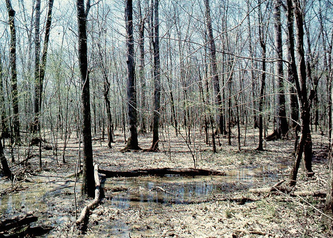 This photo shows the flood plain of the
Yockanookany River near Thomastown, Mississippi.
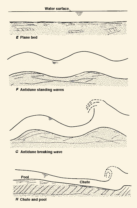
1.20 In channel flow capable of moving its own bed, the flow interacts with the boundary, producing a type of bed roughness, for example, ripples, dunes, or plane bed. 1.21 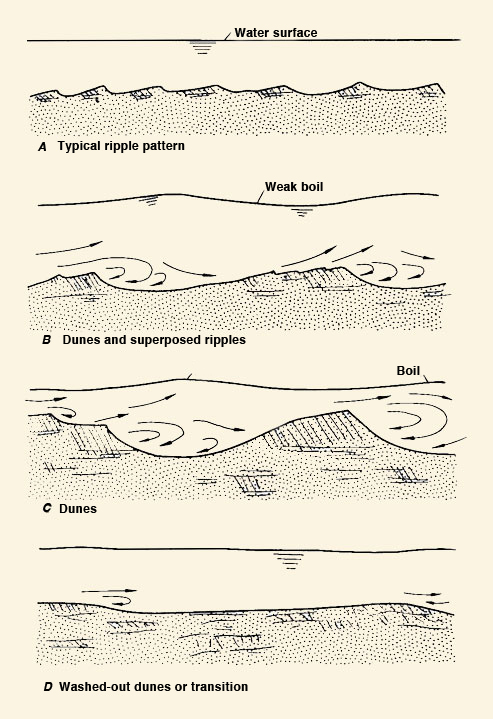
1.22 Storm sewer flow often looks like pipe flow, but generally behaves as open-channel flow. 1.23 Culverts are highway underpasses, designed to convey streamflow. 1.24 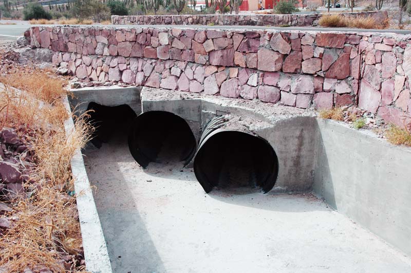
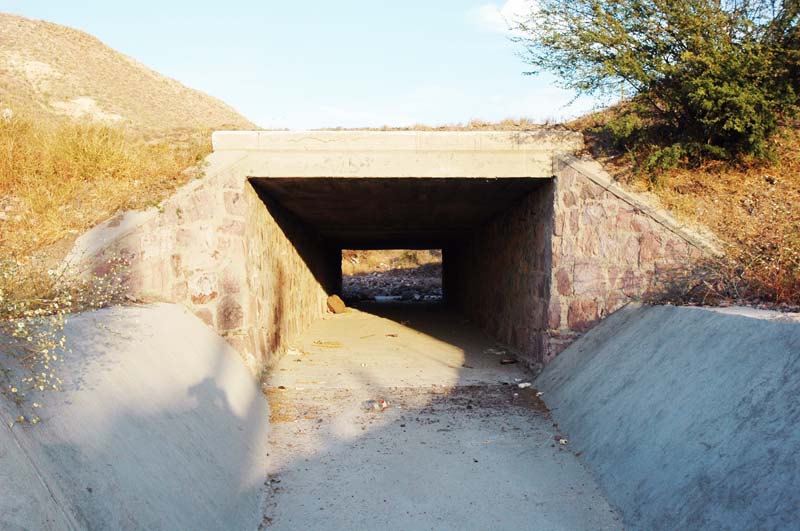
1.25 In certain cases, both pressurized and free-surface flow conditions may occur in the same culvert at different times. 2. TYPES 2.01 In open-channel flow, the channel cross sections may be (1) prismatic, or (2) non-prismatic. 2.02 Prismatic channels retain the same cross-sectional shape along the channel; non-prismatic channels vary the cross-sectional shape. 2.03 Artificial channels are usually prismatic, while natural channels are non-prismatic. 2.04 The flow variables are: Mean velocity V Flow area A Discharge Q = VA Bottom width B Top width T Wetted perimeter P Hydraulic radius R = A/P Hydraulic depth D = A/T Flow depth d Channel bottom elevation z Water surface elevation, or stage, y = z + d 2.05 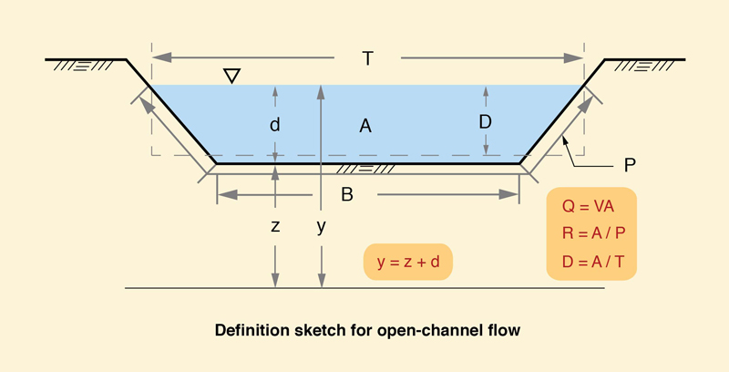
2.06 In prismatic channels, y is often used to refer to flow depth, when it cannot be confused with stage. 2.07 Open-channel flow is classified as (1) steady, or (2) unsteady. 2.08 Steady flow does not change in time; unsteady flow changes in time. 2.09 Open-channel flow is classified as (1) uniform, or (2) equilibrium. 2.10 Uniform flow describes steady flow of constant depth in a prismatic channel. 2.11 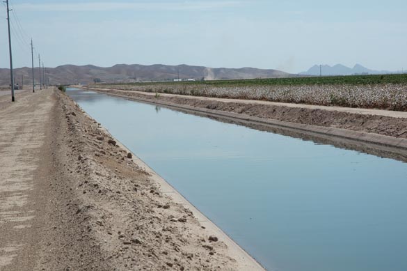
2.12 In a nonprismatic or natural channel, equilibrium flow describes steady flow in which the average water surface slope is approximately equal to the average bottom slope. 2.13 Open-channel flow is classified as (1) gradually varied, or (2) rapidly varied. 2.14 Gradually varied flow is that in which vertical accelerations are negligible. 2.15 Flow in channels without control structures is usually gradually varied flow. 2.16 Rapidly varied flow is that in which vertical accelerations are not negligible. 2.17 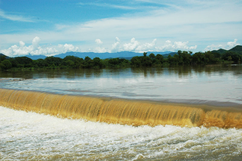
2.18 Flow in the vicinity of control structures is usually of the rapidly varied flow type. 2.19 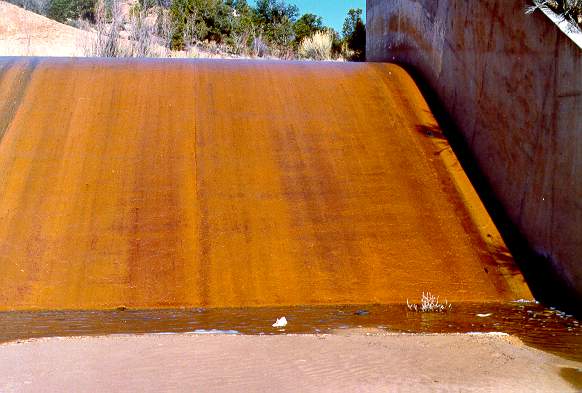 This photo shows the spillway of Sheep Creek Barrier Dam, near Cedar City, Utah.
This is a sediment retention dam built in the 1960s by the U.S. Bureau of Reclamation.
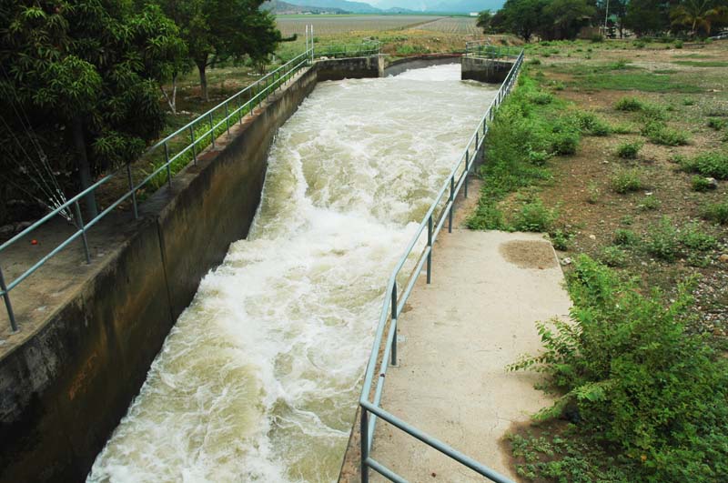
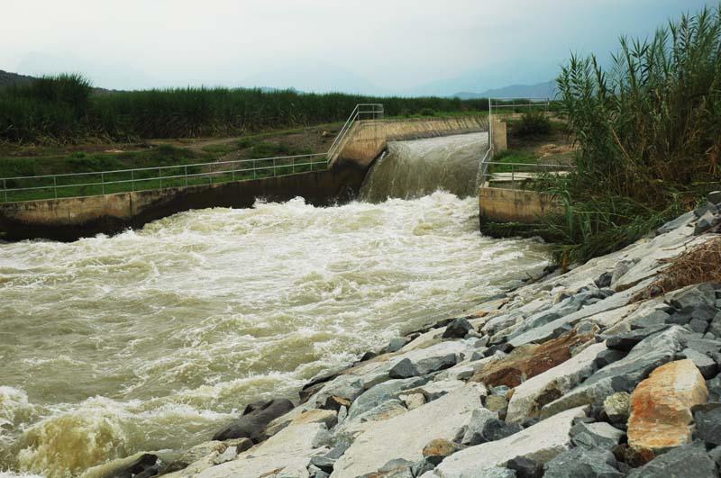
2.20 Spatially varied flow is that in which the discharge changes along the channel. 2.21 Unsteady uniform flow does not exist; open-channel flow cannot be unsteady and uniform at the same time. 2.22 Steady gradually varied flow entails the calculation of water surface profiles. 2.23 The calculation of water surface profiles is commonly referred to as a backwater computation. 2.24 Examples of steady rapidly varied flow are: (1) flow over spillways, (2) the hydraulic jump, and (3) the hydraulic drop. 2.25 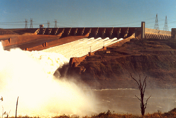
2.26 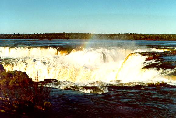 This photo shows Devil's Throat, a spectacular natural drop
at Iguazu Falls, along the border between Brazil and Argentina.
2.27 Unsteady gradually varied flow is flood waves. 2.28 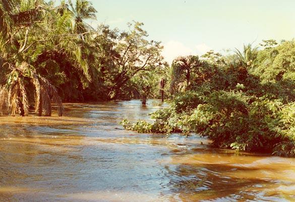 This photo shows a major flood in progress on the Chane river, near Santa Cruz, Bolivia,
on January 19, 1990.
2.29 Examples of unsteady rapidly varied flow are: (1) surges, (2) roll waves, (3) tidal bores, (4) kinematic shocks, and (5) debris flows. 2.30 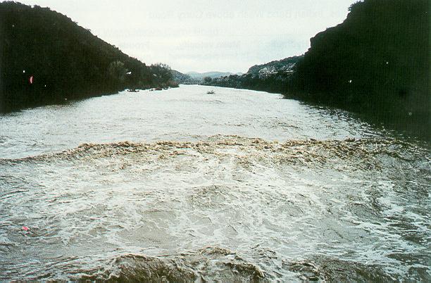
This photo shows a surface wave on the Hassayampa river, near Morristown, Arizona, during the flood of February 9, 1993. 2.31 Surges are relatively fast changes in flow depth which may originate in sudden gate closures. 2.32 Roll waves are small wave trains resulting from flow instability in steep artificial channels. 2.33 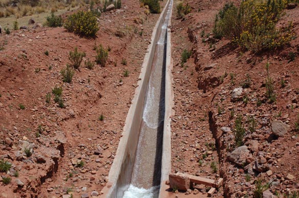 This photo shows roll waves in a lateral canal, Cabana-Mañazo irrigation project, Puno, Peru.
2.34 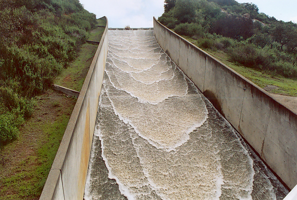 This photo shows roll waves on the spillway at Turner dam, San Diego County, California, spilling on February 24, 2005.
2.35 Tidal bores are produced at certain times of the year, in shallow estuaries featuring a large tidal range. 2.36 A tidal bore originates in the ocean and moves inland, traveling upstream in a river. 2.37 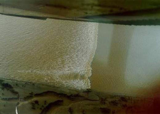 This photo shows a tidal bore ascending the Araguari river, in Amapa, Brazil,
on January 22, 1989.
2.38 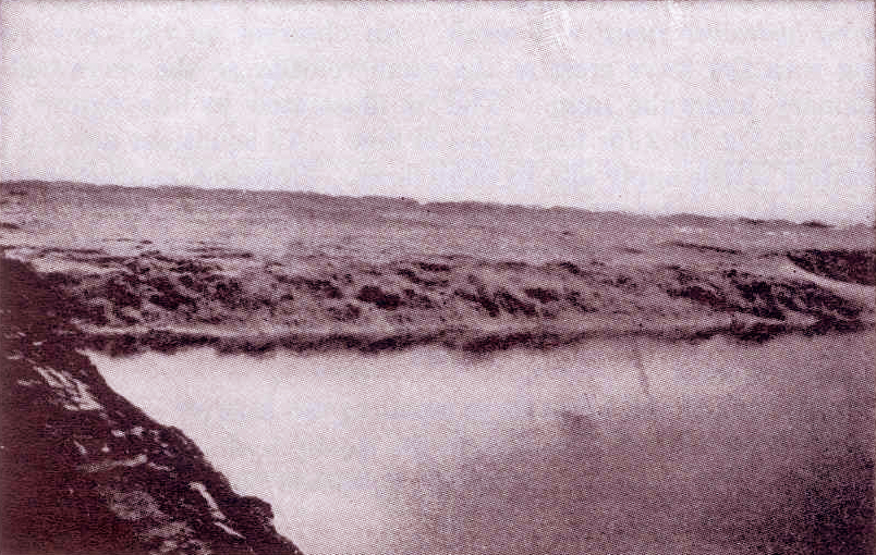 This photo shows the Hangchow bore at Haining on the Chien Tang river, China (V. T. Chow).
2.39 Kinematic shocks are flood waves that steepen while they propagate, until their rising limb becomes, for all practical purposes, a wall of water. 2.40 They occur in hydraulically wide streams under the right combination of flow conditions. 2.41 Unlike tidal bores, kinematic shocks travel downstream. 2.42 Debris flows are flood waves with a very high concentration of sediments. 2.43 
2.44 Debris flows are produced in certain regions under a gamut of geomorphological, ecological, and climatic factors, among which are: (1) steep slopes, (2) type of vegetation, (3) strong winds, (4) wildland fires, and (5) intense rains. 2.45 Lahars are a type of debris flow produced by rapid snowmelt following a volcanic eruption. 2.46 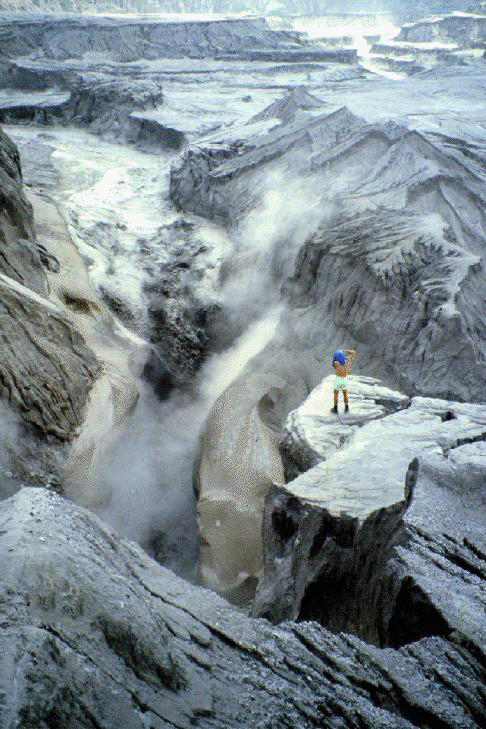
5.00  Definition sketch.
5.01  
5.02  Hassayampa river near Morristown, Arizona, on February 9, 1993 (USGS Professional Paper No. 1584).
5.03 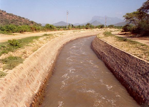 Tinajones feeder canal, Lambayeque, Peru.
5.04  Yockanookany River near Thomastown, Miss. (USGS Water Supply Paper No. 2339).
5.05 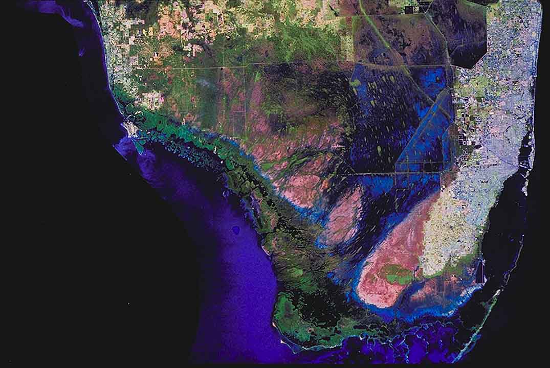 The South Florida Everglades (SFWMD).
5.06 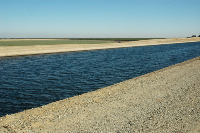 The California Aqueduct (San Luis Canal).
5.07  The Calleguas Salinity Management pipeline, under construction on September 19, 2007.
5.08  Forms of bed roughness (USGS Professional Paper No. XXX).
5.09  Forms of bed roughness (USGS Professional Paper No. XXX).
5.10  Rio La Silla Natural Park, Monterrey, Mexico.
5.12  Overflow spillway at Sheep Creek Barrier Dam, Utah.
5.13  Amazon tidal bore.
5.14  Amazon tidal bore.
5.15  Tidal bore on the Chien Tang river, China (Chow, 1959).
5.16 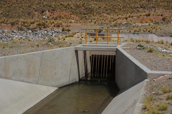 River crossing by siphon, Cabana-Mañazo Canal, Puno, Peru.
5.17 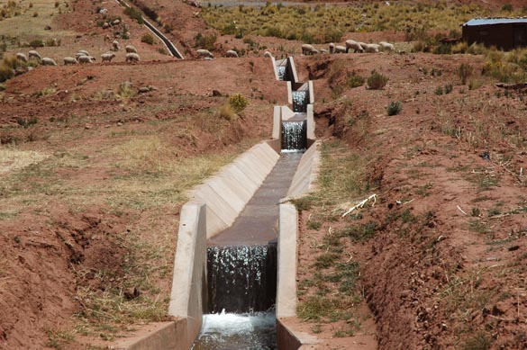 Series of canal drops, Cabana-Mañazo Canal, Puno, Peru.
5.18  Roll waves, Cabana-Mañazo Canal, Puno, Peru.
5.19  Roll waves on spillway at Turner reservoir, San Diego County, California, spilling
on February 24, 2005.
5.20  Tinajones feeder canal, Lambayeque, Peru,
5.21 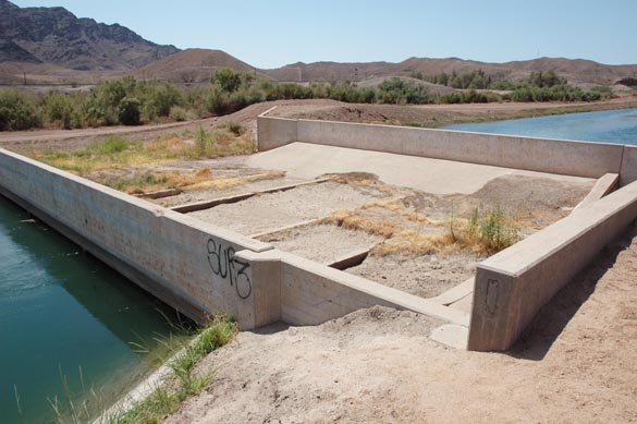 Creek bypass, Wellton-Mohawk main canal, Arizona.
5.22  Hydraulic jump at entrance to Tinajones feeder canal, Lambayeque, Peru.
5.23 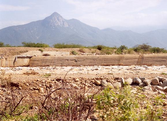 Crossing of Tinajones feeder canal with Chiriquipe Wash, Lambayeque, Peru.
5.24  Confluence of Fresh Water Canal (left) with La Cano Canal (foreground), Arequipa, Peru.
5.25  Corrugated steel culvert, La Paz, Baja California Sur, Mexico.
5.26  Concrete box culvert, La Paz, Baja California Sur, Mexico.
5.27 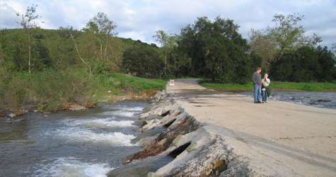 Arizona crossing, Irvine Ranch, California (Fuscoe Engineering).
5.28 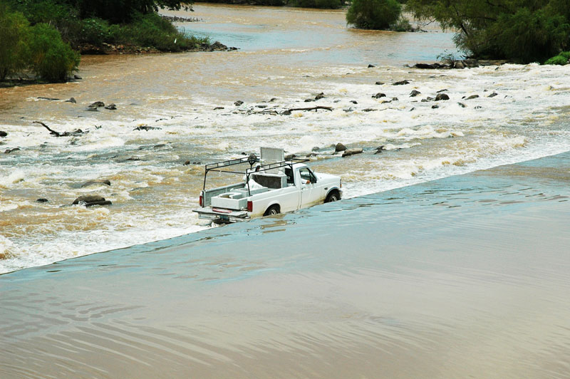 Ford in Grande de Santiago river, Nayarit, Mexico.
5.29  Ford in Jaguaribe river, Ceara, Brazil.
5.30 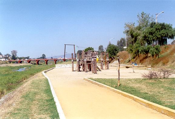 Flood plain park, Atoyac river, Oaxaca, Mexico.
5.31 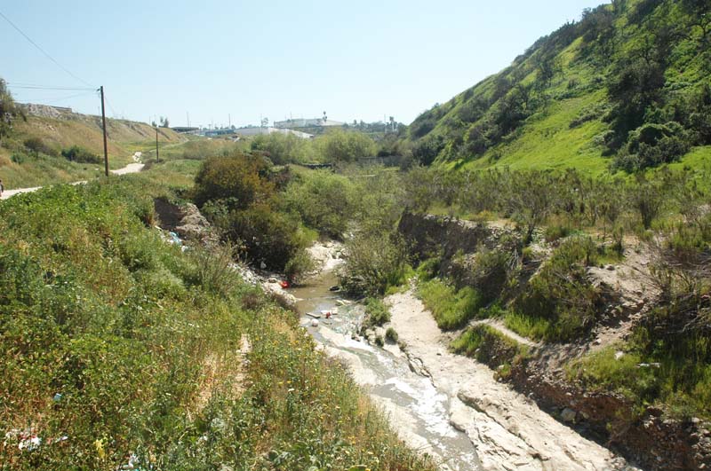 Streambed degradation to bedrock, Aguaje de la Tuna, Tijuana, Baja California, Mexico.
5.32  Wellton Mohawk main canal, Arizona.
5.33 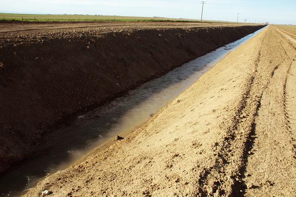 Agricultural drain, San Joaquin valley, California.
5.34  El Cora ford, Grande de Santiago river, Nayarit, Mexico.
5.35  Wellton-Mohawk irrigation canal, Arizona.
5.36  Lahar in the Lower Sacobia river, Phillipines, July 22, 1993.
5.37  Debris flow in Yunnan province, China.
5.38 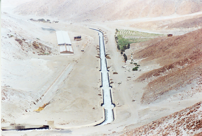 La Joya Canal, Arequipa, Peru.
5.39 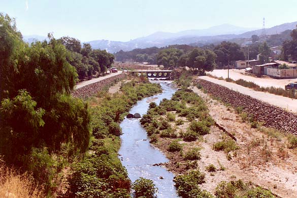 Levee on the Tecate river, Tecate, Baja California, Mexico.
5.40 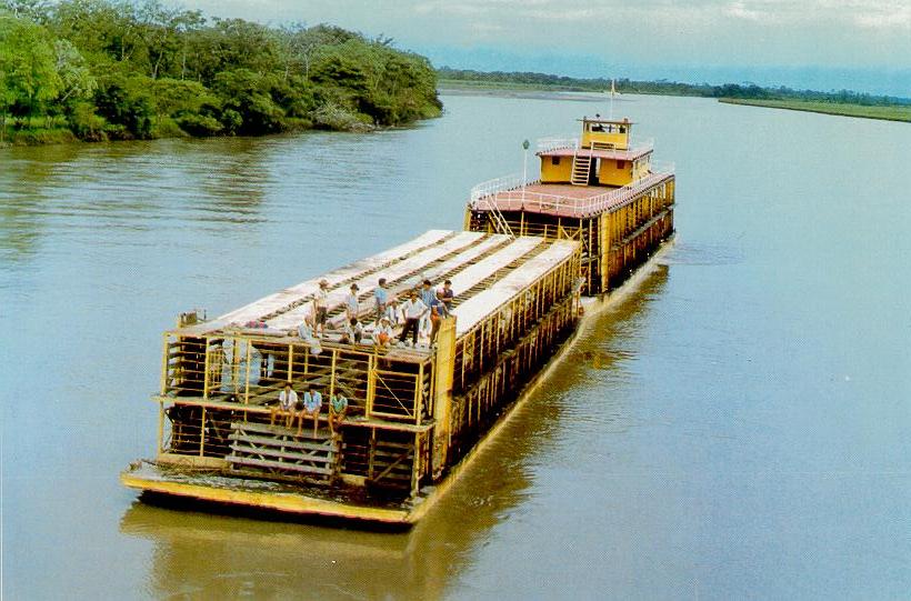 Navigation on the Meta River, Colombia.
5.41  Dulzura conduit overflowing after heavy rain on March 5, 2005, San Diego County, California.
5.42  Emergency spillway at Itaipu Dam, on the Parana river, along the border between Brazil and Paraguay.
5.43 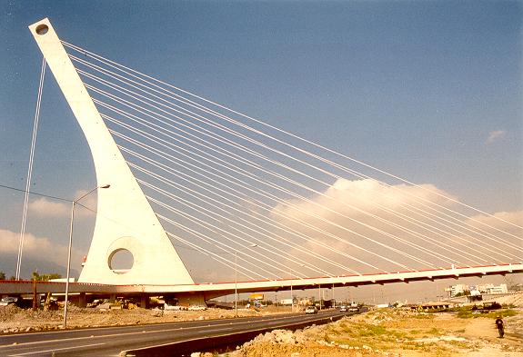 Single-abutment suspension bridge over Santa Catarina river, Monterrey, Mexico.
5.44  El Cora ford in Grande de Santiago river, Nayarit, Mexico.
5.45  Flood stage on the Chane river, Bolivia, January 19, 1990.
5.46 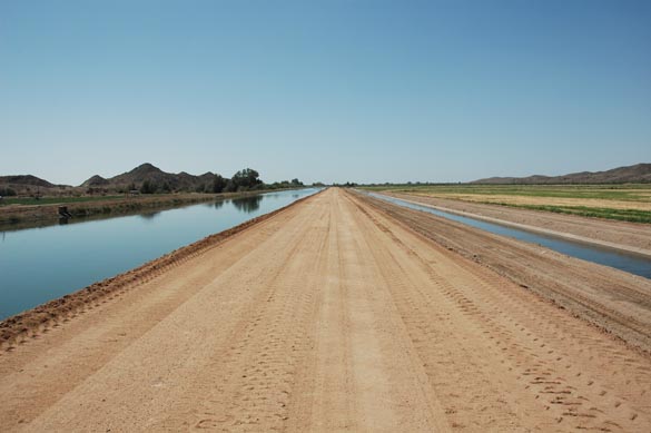 Canal and drain, Wellton-Mohawk irrigation district, near Wellton, Arizona.
5.47 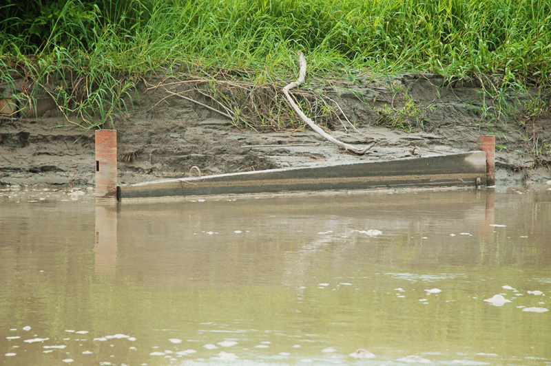 Submerged panel to control bank erosion, Metica river, Meta Department, Colombia.
5.48 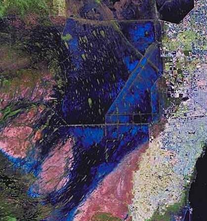 The Everglades wetland, South Florida, showing direction of flow by the alignment of elongated hummocks.
5.49 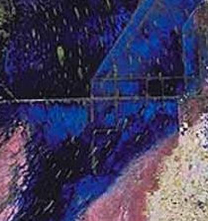 The Everglades wetland, South Florida, showing direction of flow by the alignment of elongated hummocks.
5.50  Devil's Throat at Iguazu Falls, border between between Argentina and Brazil.
5.51  Hydraulic drop in Tinajones feeder canal, Lambayeque, Peru.
5.52 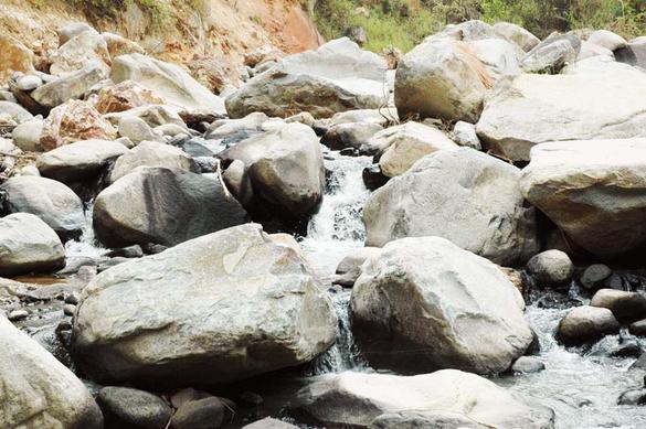 Rachichuela Creek, Lambayeque, Peru.
5.53  La Silla River Natural Park, Monterrey, Mexico.
5.54 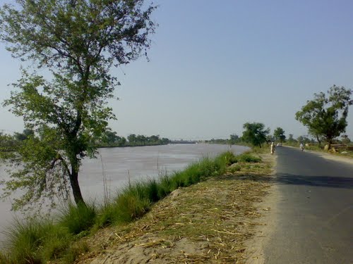 Qadirabad-Baloki Link Canal, Pakistan.
5.55 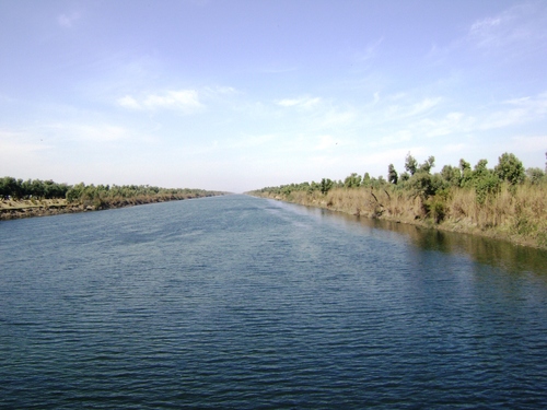 Chasma-Jhelum Link Canal, Pakistan.
Narrator: Victor M. Ponce Music: Fernando Oñate Editor: Flor Pérez
Copyright © 2011 Visualab Productions All rights reserved
|