|
OPEN-CHANNEL HYDRAULICS: LECTURE 021 - PROPERTIES OF OPEN CHANNELS
1.01 There are two kinds of channels: 1. Natural, and 2. Artificial
1.02 Artificial channels are used in various applications, among which are: 1.03 Irrigation
1.04 Drainage
1.05 Water supply
1.06 Flood control
1.07 The All-American Canal is the largest engineered canal system in the world in terms of discharge. It transfers Colorado river water from Imperial Dam, near Yuma, Arizona, to the Imperial valley, near Calexico, California.
1.08 The Indus Basin Irrigation System is among the largest water-transfer schemes in the world. It features twelve large irrigation canals linking the western to the eastern rivers of Pakistan.
1.09 Other water-resources related fields are: 1. Hydrology: The study of water in the hydrologic cycle. 2. Hydroclimatology: The study of climate and the hydrologic cycle. 3. Ecohydrology: The study of hydrology and its support of neighboring ecosystems. 4. Fluvial geomorphology: The study of the form and shape of streams and rivers. 5. River mechanics: The study of the mechanical properties and behavior of rivers. 6. Sedimentation Engineering: The theory and practice of sediment transport in the hydrologic cycle. 7. Potamology: The study of rivers.
1.10 The following are various names for engineering canals: 1. Canal: A long artificial channel, usually of mild slope, ground supported, either unlined, or lined with masonry, concrete, or asphalt. 2. Flume: A usually short canal, supported above ground, made of wood, metal, or plastic. 3. Chute: A canal of steep slope, usually supercritical.
4. Drop: A very short chute.
5. Culvert: A covered channel of comparatively short length, which may flow partially full.
2. CHANNEL GEOMETRY 2.01 A prismatic channel has a constant bottom slope and a constant cross section. 2.02 The channel section is normal to the direction of flow. 2.03 A trapezoid is the most common cross-sectional shape. For an unlined channel, it provides bank stability.
2.04 A rectangular section is commonly used in laboratory flumes. 2.05 Canals built of stable materials such as concrete can be of rectangular shape.
2.06 Triangular channels are used in ditches and road-side gutters.
3. GEOMETRIC ELEMENTS 3.01 The depth of flow y is the vertical distance from the free surface to the lowest point in the channel cross section. 3.02 The depth of flow section d is the height of the channel cross section, normal to the flow direction. 3.03 The relation between depth of flow y and depth of flow section d is:
Eq. 1
3.04 Stage is the elevation of the free surface. Stage is also referred to as y, particularly when it cannot be confused with the depth of flow.
3.05 The channel bottom elevation with reference to an arbitrary datum is referred to as z. Thus, the stage or water-surface elevation is:
Eq. 2 3.06 The flow area A is the area of flow of the channel cross section. 3.07 The mean velocity v is the average speed of the flow. 3.08 The discharge Q is the product of mean flow velocity and flow area.
Eq. 3 3.09 The bottom width B is the width of the bottom of a rectangular or trapezoidal cross section. 3.10 The top width T is the width of the channel cross section at the free surface. 3.11 The wetted perimeter P is the length along the perimeter of the channel cross section which is wetted by the flow. 3.12 The hydraulic radius is the ratio of flow area to wetted perimeter.
Eq. 4 3.13 The hydraulic depth is the ratio of flow area to top width.
Eq. 5
4. VELOCITY DISTRIBUTION 4.01 Within a channel cross section, the velocity varies vertically along the depth, and transversally across the width. 4.02 The velocities near the boundary are close to zero. This is referred to as the no-slip condition, the effect of friction along the channel boundary. 4.03 Large velocity gradients near the boundary result in substantial shear stresses, which entrain and transport sediment in unlined channels. 4.04 Channel roughness has an effect on the curvature of the vertical velocity profile. A greater roughness produces a larger curvature. 4.05 Maximum velocities occur near the surface, at 5 to 25 percent of the flow depth, measured from the top. 4.06 In channel bends, velocities are larger on the outside of the bend, and smaller on the inside. 4.07 A hydraulically wide channel is that in which the ratio of top width to hydraulic depth is greater than 10.
Eq. 6 4.08 In a hydraulically wide channel, the sides have no influence on the velocity profile. 4.09 In a hydraulically wide channel, the wetted perimeter is approximately equal to the top width.
Eq. 7 4.10 In a hydraulically wide channel, the hydraulic radius is approximately equal to the hydraulic depth.
Eq. 8 4.11 Most natural channels are hydraulically wide. 4.12 In practice, a hydraulically wide channel can be approximated as a rectangular channel of depth d and width B.
Eq. 9 4.13 A unit-width analysis is applicable in hydraulically wide channels. 4.14 The discharge per unit of channel width q is:
Eq. 10
5. VELOCITY MEASUREMENTS 5.01 Velocity measurements are usually made with a current meter. 5.02 The Price cup current meter is in common use in the United States.
5.03 Velocity measurements are made at 0.2 and 0.8 of the flow depth, and averaged to obtain a representative value. 5.04 For shallow streams, one velocity measurement at 0.6 of the flow depth, measured from the top, is usually sufficient. 5.05 The location of a streamgaging station is chosen carefully to minimize: (1) flow nonuniformities, and (2) shifts in stage-flow rating which may be caused by changes in bottom roughness, and/or erosion and sedimentation.
Fig. 01
Fig. 02
Fig. 03
Fig. 04
Fig. 05
Fig. 06
Fig. 07
Fig. 08
Fig. 09
Fig. 10
Fig. 11
Fig. 12
Fig. 13
Fig. 14
Fig. 15
Fig. 16
Fig. 17
Fig. 18
Fig. 19
Narrator: Victor M. Ponce
Music: Fernando Oñate
Editor: Flor Pérez
Copyright © 2011
Visualab Productions
All rights reserved
|
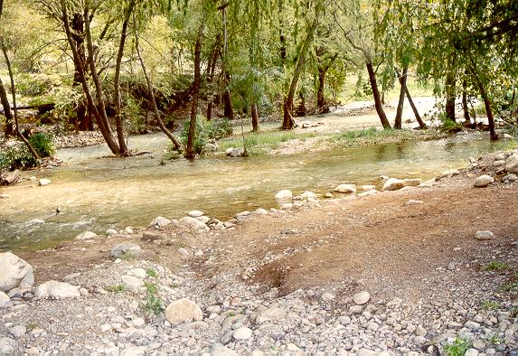 Fig. 01. La Silla River Ecological Park, Monterrey, Mexico
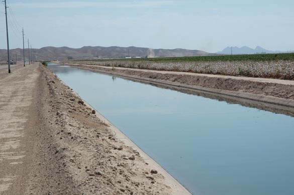 Fig. 02. Main canal, Wellton-Mohawk irrigation project, Wellton, Arizona
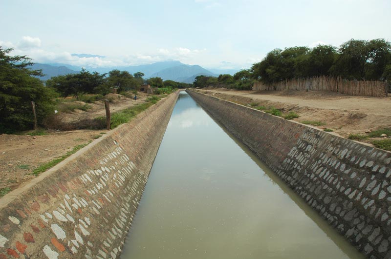 Fig. 04. Tinajones feeder canal, Peru
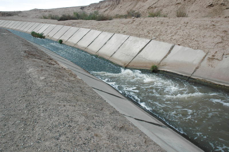 Fig. 05. Rice 3 drain, Imperial valley, California
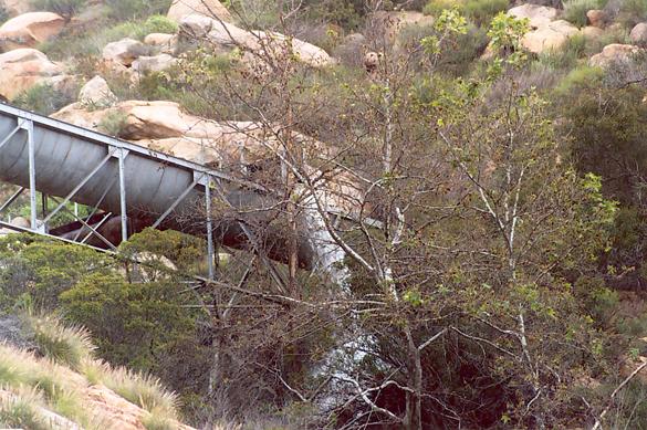 Fig. 06. Dulzura conduit, overflowing after heavy rain on March 5, 2005, San Diego County, California
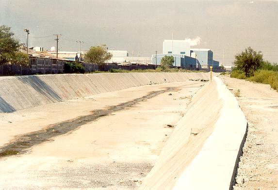 Fig. 07. Santa Catarina river, Monterrey, Mexico
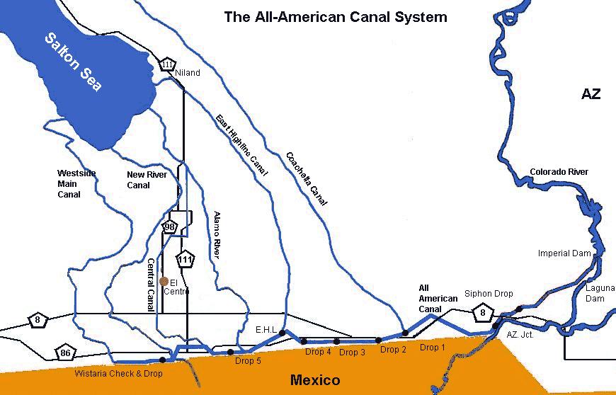 Fig. 08. The All-American Canal System
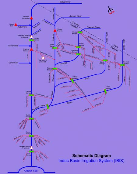 Fig. 09. The Link Canals of the Indus basin Irrigation System, Pakistan
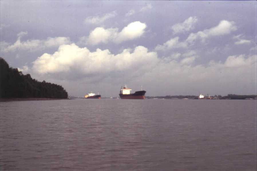 Fig. 03. Lower Mississippi river near Baton Rouge, Louisiana
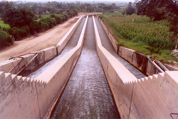 Fig. 10. Chute at Taymi Canal, Chiclayo, Peru
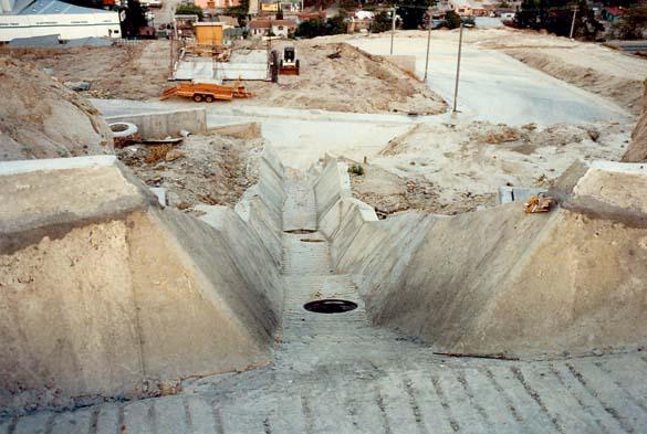 Fig. 11. Drainage drop structure, Tijuana, Baja California, Mexico
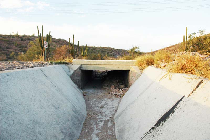 Fig. 12. Highway culvert near La Paz, Baja California Sur, Mexico
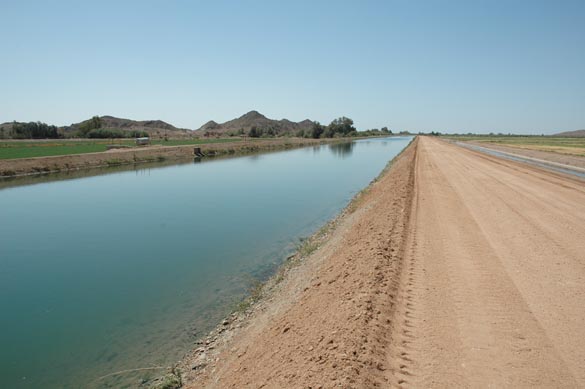 Main canal, Wellton-Mohawk irrigation project, Wellton, Arizona.
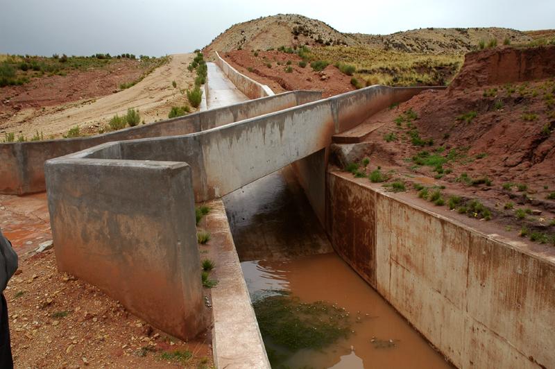 Main canal, Lagunillas Project, Puno, Peru
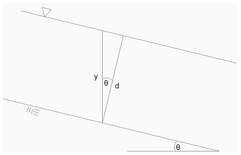 Relation between depth of flow y and depth of flow section d
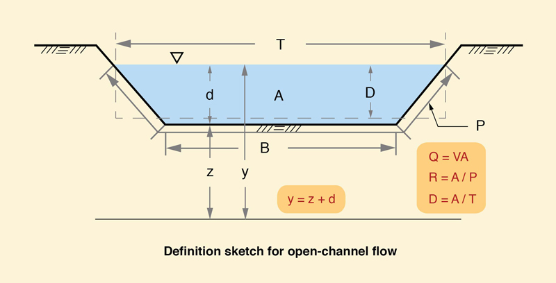 Definition sketch for geometric elements in open-channel flow.
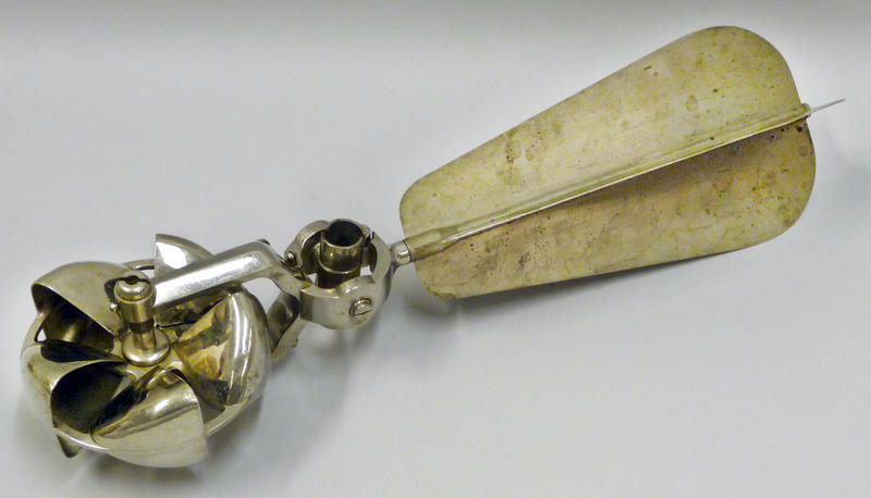 The Price current meter (U.S. Geological Survey).
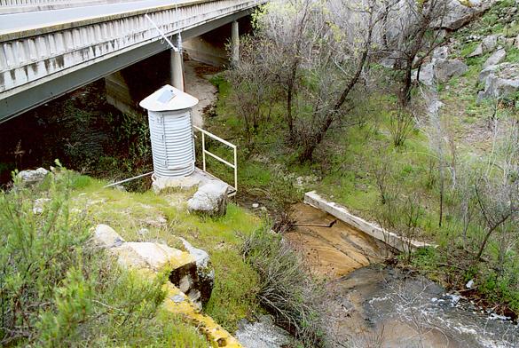 Streamgaging station at Campo Creek, San Diego County, California.
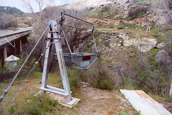 Streamgaging station at Campo Creek, San Diego County, California.