|
OPEN-CHANNEL HYDRAULICS: LECTURE 022 -
VELOCITY DISTRIBUTION COEFFICIENTS
1.01 There is nonuniformity in the velocity distribution in an open-channel cross section. 1.02 This produces a true velocity head which is somewhat greater than the velocity head calculated based on the mean velocity. 1.03 The true velocity head is:
Eq. 1 1.04 in which alpha is the energy or Coriolis coefficient, vm is the mean velocity, and g is the gravitational acceleration.
1.05 Typically, alpha varies in the range 1.03-1.36 for fairly straight prismatic channels. 1.06 Alpha is larger for smaller channels, and smaller for larger channels. 1.07 As in the case of energy, the true momentum flux is somewhat greater than the momentum flux calculated based on the mean velocity. 1.08 The true momentum flux is:
Eq. 2 1.09 in which beta is the momentum or Boussinesq coefficient, ρ is the density of water and Q is the discharge. 1.10 Typically, beta varies in the range 1.01-1.12 for fairly straight prismatic channels. 1.11 Alpha is always greater than beta. 1.12 In channels of complex cross section, alpha and beta can attain values of 1.6 and 1.2, respectively. 1.13 Values of alpha greater than 2 have been observed in very irregular cross sections.
2. DERIVATION OF α 2.01 Assume: A = total area of the cross section vm = mean velocity of the cross section ΔA = incremental area v = velocity through the incremental area 2.02 The total volumetric flux or discharge is:
Eq. 3 2.03 The total weight flux is:
Eq. 4 2.04 in which γ is the unit weight of water.
2.05 The incremental weight flux is:
Eq. 5 2.06 The kinetic energy is equal to force times distance, that is, mass times acceleration times distance. It is expressed as follows:
Eq. 6
2.07 in which m is the mass of water.
2.08 The velocity head is the kinetic energy per unit of weight.
Eq. 7
2.09 The kinetic energy flux is the kinetic energy per unit of weight times the weight flux. That is, the kinetic energy flux is equal to the velocity head times the weight flux. 2.10 The total kinetic energy flux is:
Eq. 8
Eq. 9
2.11 Likewise, the kinetic energy flux through an incremental area ΔA is:
Eq. 10
2.12 The total energy flux is equal to the sum of the incremental energy fluxes.
Eq. 11
2.13 Thus, the energy or Coriolis coefficient alpha is:
Eq. 12 3. DERIVATION OF β 3.01 The total mass flux is:
Eq. 14 3.02 The incremental mass flux is:
Eq. 15 3.03 The momentum is equal to force times time, that is, mass times acceleration times time. It is expressed as follows:
Eq. 16 3.04 The momentum flux or force is equal to the mass flux times the velocity.
Eq. 17 3.05 The total momentum flux is equal to the total mass flux times the velocity.
Eq. 18 3.06 The incremental momentum flux or incremental force is equal to the incremental mass flux times the velocity.
Eq. 19
3.07 The total force is equal to the sum of the incremental forces.
Eq. 20
3.08 Thus, the momentum or Boussinesq coefficient β is:
Eq. 21
3.09 The mean velocity is defined as:
Eq. 22
3.10 Values of alpha and beta can be approximately estimated with the following relations:
Eq. 23
Eq. 24 3.11 in which epsilon is:
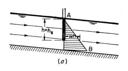
Eq. 25 4. PRESSURE DISTRIBUTION 4.01 The pressure is measured by the height of the water column at any point in the vertical. 4.02 Under parallel flow, the streamlines have zero curvature and zero vertical accelerations. Fig. 01
4.03 Conversely, under curvilinear flow, the streamlines have nonzero curvature and nonzero vertical accelerations. 4.04 Under parallel flow, the pressure distribution is hydrostatic, that is, the pressure p at any point is proportional to the flow depth h at that point.
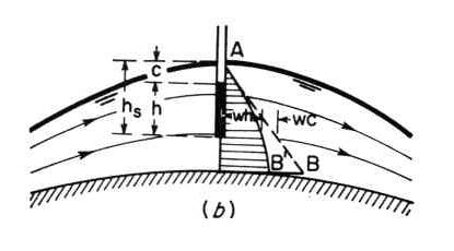
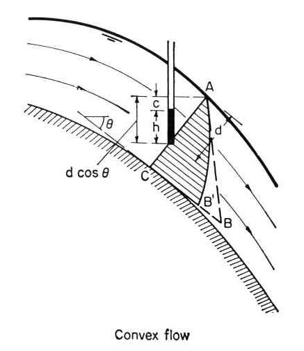
Eq. 26 4.05 Uniform flow is essentially parallel flow. 4.06 Gradually varied flow may be approximated as parallel flow. 4.07 Under curvilinear flow, the pressure distribution is not hydrostatic. 4.08 Curvilinear flow can be either: (1) convex, or (2) concave. 4.09 Under convex curvilinear flow, the pressure distribution is less than hydrostatic. Fig. 02
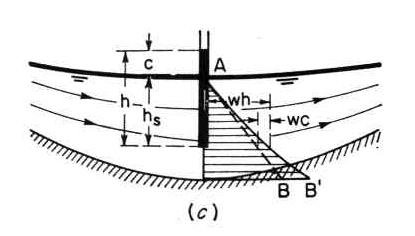
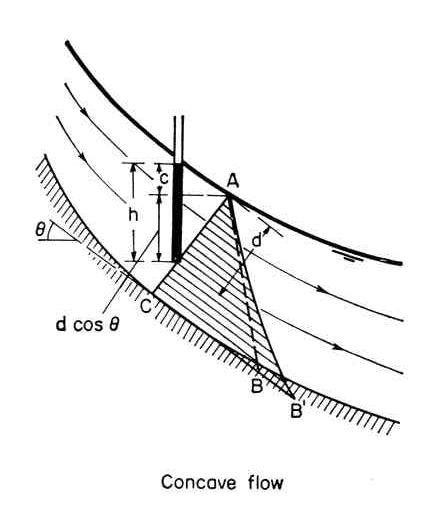
4.10 Under concave curvilinear flow, the pressure distribution is in excess of hydrostatic. Fig. 03
4.11 The centrifugal pressure is the mass per unit of area times the centrifugal acceleration.
Eq. 27 4.12 in which r = radius of curvature of streamlines. 4.13 The pressure rise c is:
Eq. 28
4.14 The rise is positive for concave flow, and negative for convex flow. Fig. 03
Fig. 02
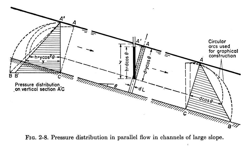
5. EFFECT OF SLOPE 5.01 The weight of the shaded element of length dL and width 1 is:
Eq. 29 Fig. 04
5.02 In terms of depth of flow y:
Eq. 30 5.03 The pressure due to this weight is:
Eq. 31 5.04 The pressure head is:
Eq. 32 5.05 If θ is small, the factor cos2 θ will be very close to unity, and the pressure head h will be close to the flow depth y. 5.06 The correction is less than 1 percent when θ is less than 6 degrees, that is, the slope is less than 10 percent, or 0.1. 5.07 A channel of slope greater than 0.1 is a channel of large slope. 5.08 In a channel of large slope with appreciable curvature in the streamlines, the pressure head should be corrected for curvature effects. Fig. 05
Fig. 06
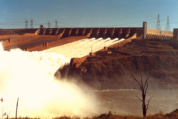
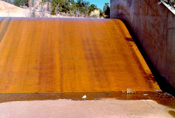
5.09 High flow velocities entrain air, producing volume swell and depth increase. Fig. 08
Fig. 07
Fig. 01
Fig. 02
Fig. 03
Fig. 04
Fig. 05
Fig. 06
Fig. 07
Fig. 08
Narrator: Victor M. Ponce
Music: Fernando Oñate
Editor: Flor Pérez
Copyright © 2011
Visualab Productions
All rights reserved
|
