|
OPEN-CHANNEL HYDRAULICS: LECTURE 041 - CRITICAL FLOW
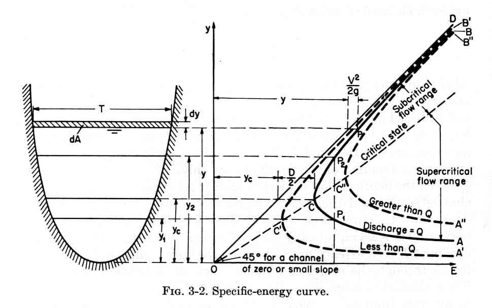
1.01 The following flow conditions characterize critical flow: 1. The specific energy is a minimum for a given discharge.
Fig. 01
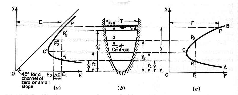
2. Discharge is a maximum for a given specific energy. 3. The specific force is a minimum for a given discharge.
Fig. 02
4. Discharge is a maximum for a given specific force. 5. The velocity head is equal to half of the hydraulic depth.
Eq. 1 6. The mean velocity is equal to the relative celerity of dynamic waves.
Eq. 2 7. The Froude number is equal to 1.
Eq. 3
1.02 The celerity of dynamic waves is:
Eq. 4
1.03 The celerity of dynamic waves, relative to the flow, is:
Eq. 5
1.04 Positive waves move with the flow; they are primary waves. 1.05 Negative waves move against the flow; they are secondary waves.
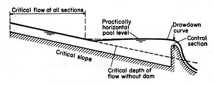
1.06 Under critical flow, secondary waves remain stationary. Fig. 03
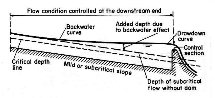
1.07 Under subcritical flow, secondary waves are able to move upstream.
1.08 Under supercritical flow, secondary waves can only move downstream.
1.09 Subcritical flow is controlled from a downstream section, since secondary surface waves are able to move upstream. Fig. 04
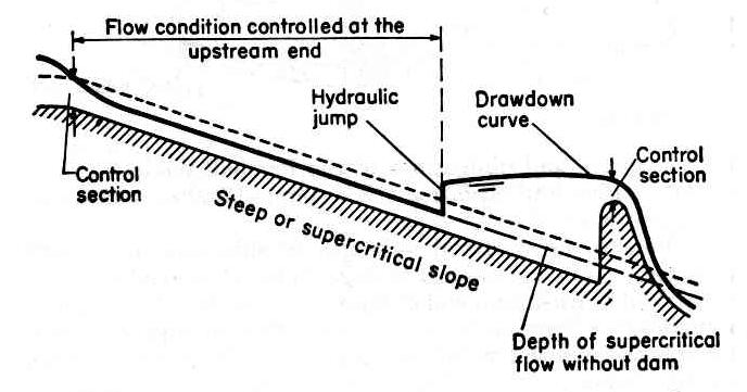
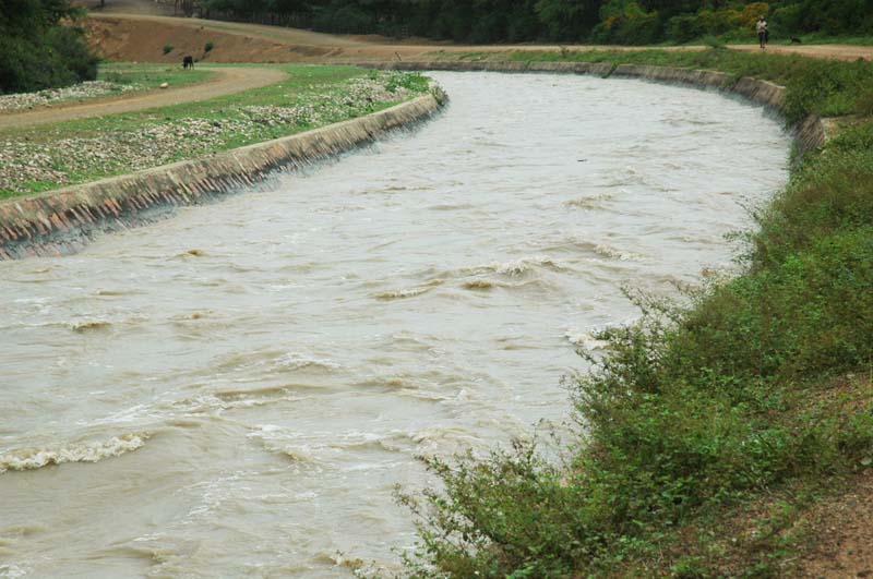
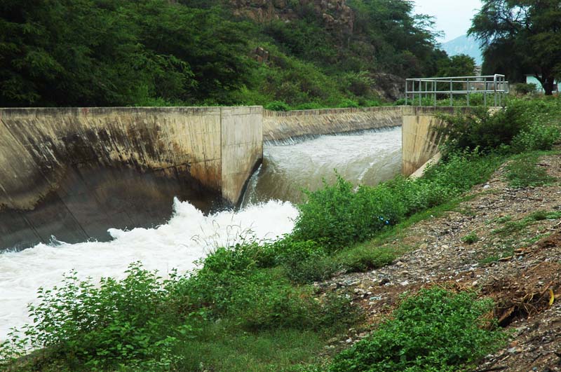
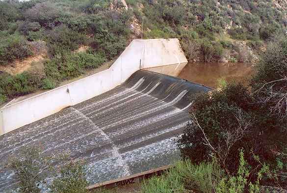
1.10 Supercritical flow is controlled from an upstream section only, since secondary surface waves are not able to move upstream. Fig. 05
1.11 Critical depth can occur in two modes: 1. Along the channel, in uniform flow, and 2. At a cross section, in either gradually or rapidly varied flow.
1.12 A channel where critical depth occurs throughout its length is a critical channel. Fig. 06
1.13 The slope of the critical channel is the critical slope Sc.
1.14 The cross section where critical flow occurs is the critical cross section. Fig. 07
1.15 The friction relation for uniform flow in a hydraulically wide channel is:
Eq. 6
1.16 in which So is the bottom slope, or bed slope, and f is an open-channel friction factor equal to 1/8 of the Darcy-Weisbach friction factor.
1.17 Under critical flow, the Froude number is equal to 1. Thus, the friction equation reduces to:
Eq. 7
1.18 In other words, the friction factor and the critical slope are one and the same.
1.19 For applications to gradually varied flow, it is convenient to recast the friction relation as:
Eq. 8
1.20 In natural channels, critical flow appears to be a self-regulating upper limit to the Froude number. 1.21 This is because as friction increases due to bedform roughness, the Froude number cannot continue to increase and still satisfy the friction equation.
1.22 In artificial channels, with no bedform roughness, supercritical flow is possible. Fig. 09
2. COMPUTATION 2.01 Under critical flow, the Froude number is equal to 1.
Eq. 9 2.02 For computational convenience, we square the Froude number.
Eq. 10 2.03 From continuity v = Q/A, and hydraulic depth D = A/T:
Eq. 11 2.04 This equation can be expressed as:
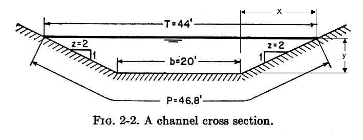
Eq. 12 2.05 In a typical prismatic channel, the input hydraulic variables for critical flow are: 1. Discharge Q, 2. Bottom width b, and 3. Side slope z: z horizontal to 1 vertical
Fig. 08
2.06 For b different than zero, and z different than zero, the channel is trapezoidal. 2.07 For z = 0, the channel is rectangular. 2.08 For b = 0, the channel is triangular. 2.09 The top width is:
Eq. 13
2.10 The flow area is:
Eq. 14
2.11 Substituting into the critical flow equation:
Eq. 15
2.12 Given the input variables Q, b, and z, this equation is solved for the critical flow depth by iteration.
Fig. 01
Fig. 02
Fig. 03
Fig. 04
Fig. 05
Fig. 06
Fig. 07
Fig. 08
Fig. 09
Narrator: Victor M. Ponce Music: Fernando Oñate Editor: Flor Pérez
Copyright © 2011 Visualab Productions All rights reserved
|
