|
OPEN-CHANNEL HYDRAULICS: LECTURE 055 - CHANNEL DESIGN
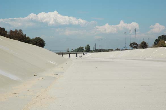
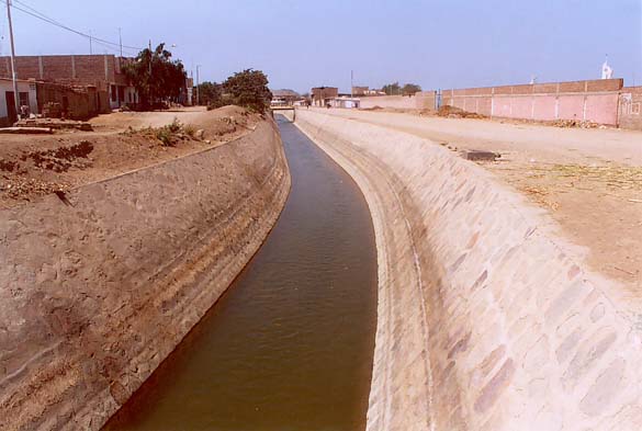
1. NONERODIBLE CHANNELS 1.01 Channels can be lined or unlined. 1.02 Lined channels are nonerodible; unlined channels are erodible. 1.03 The following factors are considered when designing nonerodible channels: 1. Lining material 2. Velocities 3. Slopes 4. Freeboard 1.04 The nonerodible lining materials can be concrete, stone masonry, steel, cast iron, timber, glass, and plastic. Fig. 01
Fig. 02
1.05 There is a minimum velocity to avoid sediment deposition. 1.06 The minimum velocity should be such that it guarantees the motion of suspended load. 1.07 The Shields criterion of river mechanics describes the initiation of motion. 1.08 In practice, a Froude number equal to 0.08 or greater will usually guarantee initiation of motion. 1.09 Values of Froude number less than 0.08 should be checked to verify initiation of motion. 1.10 The minimum velocity to prevent the growth of vegetation is 0.75 m/s. 1.11 For most applications, the design velocity is kept below critical, that is, below a Froude number equal to 1. 1.12 This limits the design velocity to a practicable maximum. 1.13 The design bottom slope usually follows the terrain's slope. 1.14 The actual design bottom slope may depend of the purpose of the channel. 1.15 Channels used for irrigation and hydropower may require small bottom slopes in order to conserve hydraulic head. 1.16 For nonerodible channels, the side slopes may be as steep as practicable. 1.16 U.S. Bureau of Reclamation practice for side slope is z = 1.5, that is, z Horizontal to 1 Vertical. 1.17 For erodible channels, the side slopes depend on the material forming the channel. 1.18 Recommended side slopes are shown in this table.
1.19 Freeboard is the vertical distance from the top of the channel to the design water surface elevation. 1.20 The freeboard is designed to prevent waves from overtopping the channel. 1.21 Freeboards varying from 5 to 30 percent of the flow depth are common. 1.22 In addition, an adequate freeboard provides protection against eventual flows greater than the design condition. 1.23 Typical U.S. Bureau of Reclamation practice is 1 ft for small canals, to 4 ft for large canals. 1.24 In addition, the Bureau of Reclamation uses this formula for freeboard:
Eq. 1
1.25 in which C varies from 1.5 for low discharges (20 cfs) to 2.5 for high discharges (3000 cfs or greater).
1.26 In theory, the best hydraulic section is the cross-sectional shape that has the minimum wetted perimeter, that is, the maximum conveyance.
1.27 Mathematically, this produces a half hexagon. In practice, other criteria may be more important than maximum conveyance.
1.28 In a typical design case, the discharge Q, bottom width b, side slope z, bottom slope S, and Manning's n are known in advance.
1.29 Then, the normal depth is calculated using normal depth formulas.
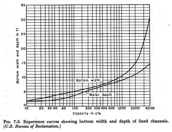
1.30 An online normal depth calculator is: ponce.sdsu.edu/onlinechannel01.php 1.31 Bureau of Reclamation experience curves for design bottom width and water depth are shown here. Fig. 03
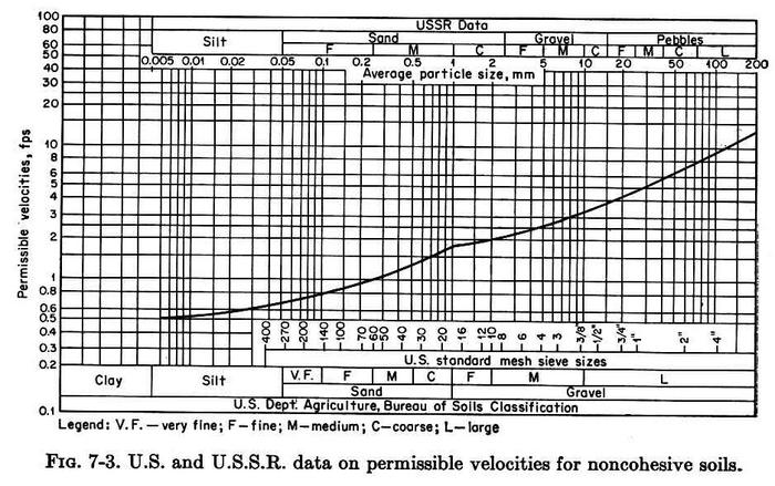
2. ERODIBLE CHANNELS 2.01 Erodible channels are unlined earthen channels, which may be subject to erosion by the force of the flow. 2.02 The design of erodible channels is substantially more complex than that of nonerodible channels. 2.03 Particle entrainment is a function of bottom shear, which is proportional to the velocity. 2.04 Excessive bottom shear and velocity can cause erosion. 2.05 Erodible channels are designed using two methods: 1. Permissible velocity. 2. Permissible tractive force. 2.06 There is an upper limit to the velocity, above which erosion will occur. 2.07 This upper limit is referred to as the maximum permissible velocity. 2.08 This velocity is estimated from experience. 2.09 For the same discharge, a deeper channel will convey water with a smaller velocity and, therefore, with less chance of erosion. 2.10 For noncohesive soils, permissible velocities vary from 0.5 ft per second for silt, to 1 ft per second for sand, and up to 10 ft per second for large gravel, as shown here. Fig. 04
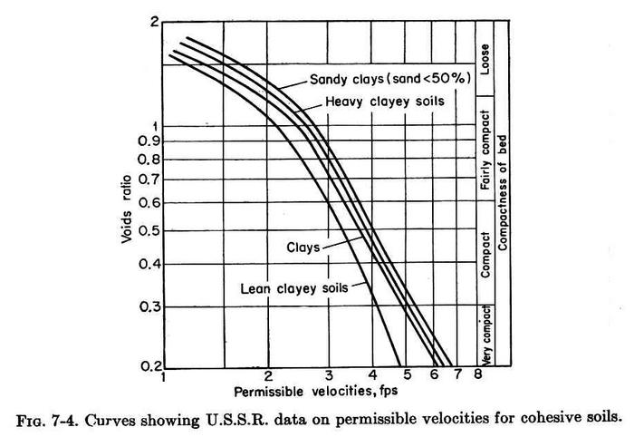
2.11 For cohesive soils, permissible velocities vary degree of compactness, from 1 ft per second for high voids ratio, to 7 ft per second for low voids ratio, as shown here. Fig. 05
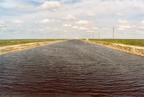
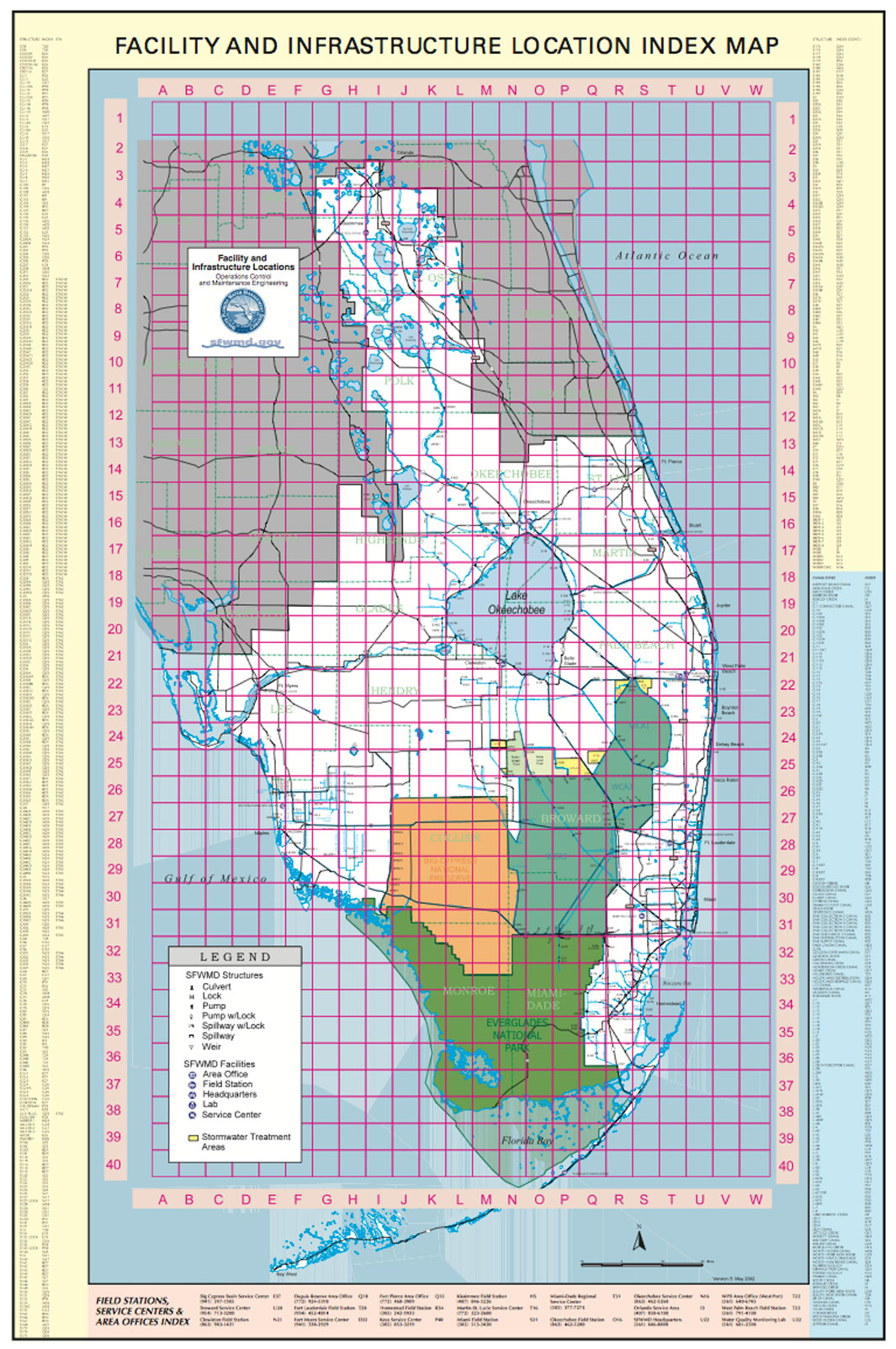
2.12 For sinuous channels, the permissible velocity may be reduced by up to 22 percent. 2.13 In a typical design application, a maximum permissible velocity is established. 2.14 Given discharge Q, an assumed bottom width b, side slope z, bottom slope S, and Manning's n, the normal depth and velocity are calculated. 2.15 The calculated velocity is compared with the maximum permissible velocity. 2.16 If the calculated velocity exceeds the maximum permissible, the assumed bottom width is too short. 2.17 If the calculated velocity does not exceed the maximum permissible, the assumed bottom width may be too long. 2.18 Assume a new bottom width and recalculate the normal depth and velocity, until a match of normal and maximum permissible velocities is obtained. 2.19 This photo shows the G-370 Canal, one of several large artificial canals operated by the South Florida Water Management District within the area of influence of the Everglades Wetlands. Fig. 07
Fig. 01
Fig. 02
Fig. 03
Fig. 04
Fig. 05
Fig. 06
Fig. 07
Narrator: Victor M. Ponce Music: Fernando Oñate Editor: Flor Pérez
Copyright © 2011 Visualab Productions All rights reserved
|
