|
OPEN-CHANNEL HYDRAULICS: LECTURE 062 - TRACTIVE FORCE METHOD
1. TRACTIVE FORCE 1.01 The tractive force method is an alternative to the permissible velocity method for the design of erodible channels. 1.02 The tractive force method has a strong theoretical and empirical basis. 1.03 The quadratic resistance law is:
Eq. 1
1.04 in which τo is the bottom shear stress or tractive stress, ρ is the density of the water, f is the dimensionless Chezy friction factor, and v is the mean velocity.
1.05 Replacing the mean velocity for its expression following Chezy:
Eq. 2
1.06 in which R is the hydraulic radius and S is the bottom slope. Replacing ρ = γ/g:
Eq. 3
1.07 which reduces to:
Eq. 4
1.08 For a hydraulically wide prismatic channel, for which the hydraulic radius may be approximated as the flow depth, the tractive stress is:
Eq. 5
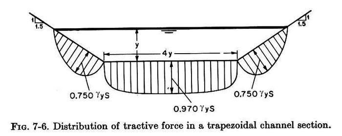
1.09 The actual value of tractive stress is:
Eq. 6
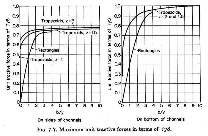
1.10 where C is either Cs, applicable to the channel sides, or Cb, applicable to the channel bottom.
Fig. 01
1.11 The variation of C is shown here, for the sides on the left, and for the bottom on the right.
Fig. 02
1.12 This figure shows that the full value of tractive stress is developed for a hydraulically wide channel, for which the ratio of bottom width to depth is greater than 10.
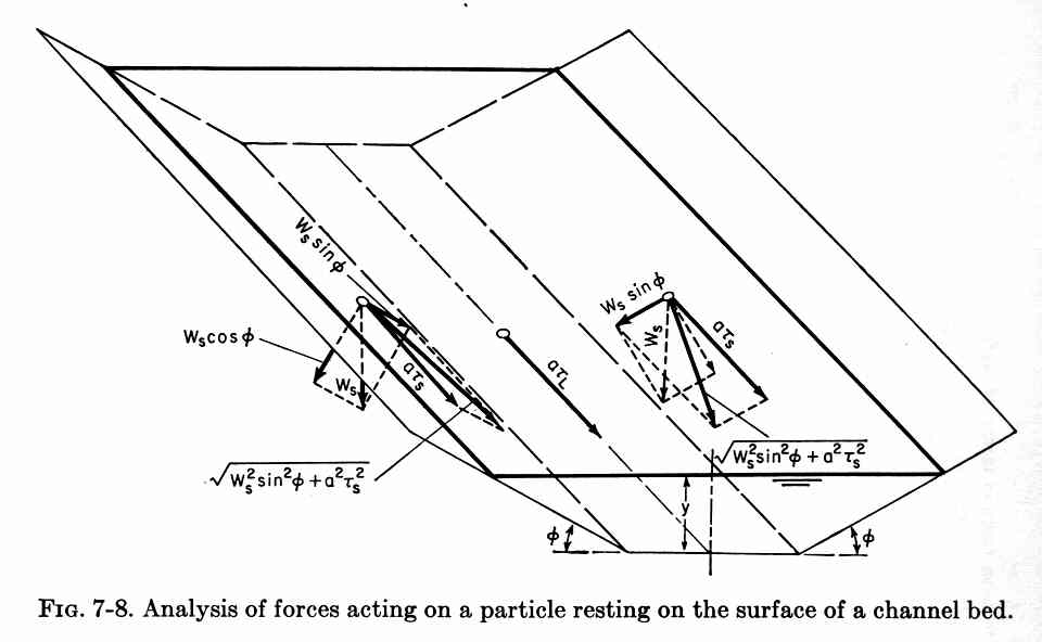
2. TRACTIVE FORCE RATIO 2.01 The tractive force method uses the tractive stress ratio. 2.02 The tractive stress ratio is the ratio of tractive stress on the channel sides τs to tractive stress on the channel bottom, that is, on level ground, τL. 2.03 τs is a function of friction angle of the material and side slope of the channel, while τL is only a function of the friction angle. 2.04 Static equilibrium leads to the tractive stress on the sides:
Eq. 7
Fig. 03
2.05 in which Ws is the submerged weight of the particle, a is the effective area of the particle, θ is the particle friction angle, and φ is the channel side slope.
2.06 On a level surface, with φ = 0, the tractive stress reduces to:
Eq. 8
2.07 The tractive force ratio is:
Eq. 9
Eq. 10
2.08 This formula is reduced by using the appropriate trigonometric identities to:
Eq. 11
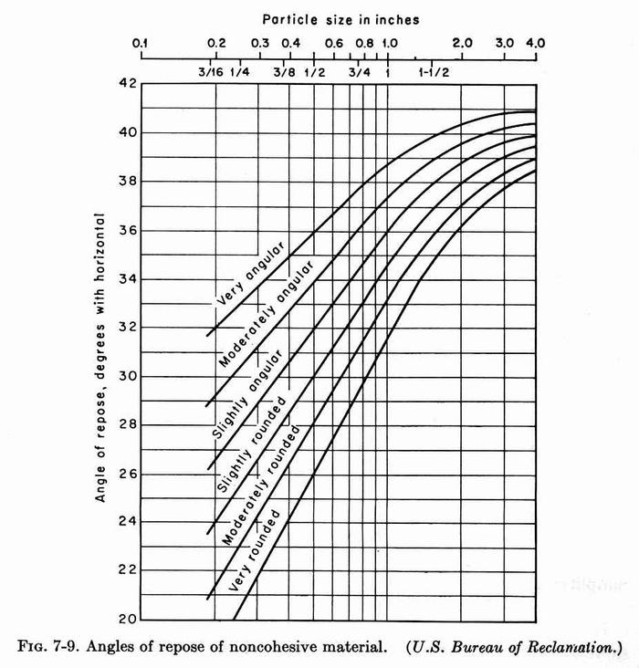
2.09 The friction angle, or angle of repose of noncohesive materials is shown here. The applicable particle size is that for which 25 percent of the material, by weight, is larger.
Fig. 04
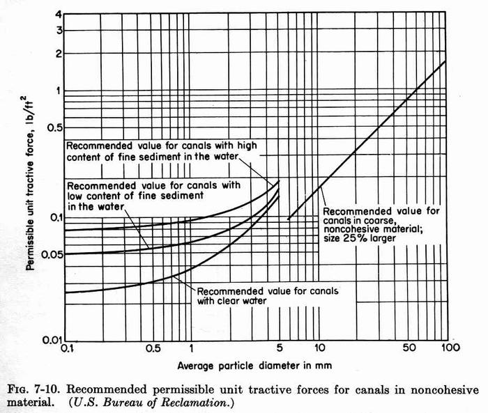
3. PERMISSIBLE TRACTIVE STRESS 3.01 The permissible tractive stress is the maximum shear stress that will not cause erosion on a level surface. 3.02 This value, obtained from laboratory experiments, is called the critical tractive stress. 3.03 This figure shows critical tractive stresses for noncohesive materials, as a function of particle size, with the sand-size materials shown to the left, and the gravel-size materials to the right. Fig. 05
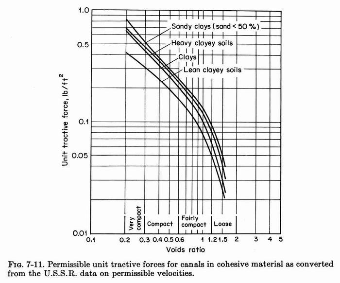
3.04 Note that for the sand-size materials, the critical tractive stress is a function of the content of fine sediment in the water. 3.05 The higher values of critical shear stress correspond to canals with high content of fine sediment. 3.06 The lower values of critical shear stress correspond to canals with low content of fine sediment. 3.07 The lowest values of critical shear stress correspond to clear water. 3.08 This is the principle of "hungry water." The freer the water is from fine sediment, the more it will have a tendency to pick up sediments; consequently, the lower the critical shear stress. 3.09 This figure shows critical tractive stresses for cohesive materials, as a function of voids ratio. Higher voids ratio corresponds to lower critical shear stress, and vice versa. Fig. 06
3.10 For sinuous channels, the values of critical shear stress are reduced to account for scour.
3.11 A 10 percent reduction is recommended for slightly sinuous channels, 25 percent for moderately sinuous, and 40 percent for very sinuous. 4. METHODOLOGY 4.01 The steps in the application of the tractive force method are the following: 1. Assume b/y and z, given Q, S, and n. 2. Assume that the tractive force on the sides is controlling the design, which is the case when the material is the same on both sides and bottom. When the materials in sides and bottom are different, the tractive force on the sides may not always be controlling the design. When the material on the sides is stronger than the material on the bottom, the tractive force on the bottom may be controlling the design. 3. Calculate the coefficient Cs of the acting shear stress Τs = Cs γ y S. 4. Determine the friction angle θ, based on particle size or voids ratio. 5. Calculate the side angle φ = arc tan (1/z) 6. Calculate the tractive stress ratio K. 4.02 7. Calculate the critical shear stress on level ground τL. 8. Calculate the critical shear stress on the sides τs = K τL 9. Set critical shear stress τs equal to acting shear stress Ts, and solve for flow depth y. 4.03 10. With y and b/y, calculate b. 11. With Q, b, z, S, and n, calculate the normal depth yn. 12. If yn is larger than y, assume a larger b/y and repeat the procedure. 4.04 13. If yn is smaller than y, assume a smaller b/y and repeat the procedure. 14. Continue the iterative process until the calculated normal depth yn matches the depth y obtained from equating acting and critical shear stresses. Fig. 01
Fig. 02
Fig. 03
Fig. 04
Fig. 05
Fig. 06
Narrator: Victor M. Ponce Music: Fernando Oñate Editor: Flor Pérez
Copyright © 2011 Visualab Productions All rights reserved
|
