|
OPEN-CHANNEL HYDRAULICS: LECTURE 073 - DIRECT-STEP METHOD
1. DATA 1.01 Here we the describe the direct-step method to calculate an M2 water-surface profile. 1.02 A similar procedure is applicable for all other water-surface profiles. 1.03 Assume a prismatic channel with the following hydraulic data: 1. Discharge Q = 1627.5 m3/s 2. Bottom width b = 100 m 3. Side slope z = 0 4. Bottom slope So = 0.000197 5. Manning's n = 0.025.
1.04 Using this data, we calculate the critical depth and normal depth. Critical depth yc = 3 m Normal depth yn = 8 m
1.05 To illustrate the procedure, we choose 10 depth intervals, each of 0.5 m, to cover the difference from critical flow, 3 m, to normal flow, 8 m.
1.06 At the first or critical depth, for y = 3 m, we calculate: 1. Area
Eq. 1
2. Velocity
Eq. 2
3. Velocity head
Eq. 3
4. Specific head
Eq. 4
5. Wetted perimeter
Eq. 5
6. Hydraulic radius
Eq. 6
7. Friction slope
Eq. 7
1.07 The second depth is equal to the first depth, 3.0 m, plus the depth interval, 0.5 m. Thus, the second depth is 3.5 m.
1.08 At the second depth, for y = 3.5 m, we calculate: 1. Area
Eq. 8
2. Velocity
Eq. 9
3. Velocity head
Eq. 10
4. Specific head
Eq. 11
5. Wetted perimeter
Eq. 12
6. Hydraulic radius
Eq. 13
7. Friction slope
Eq. 14
1.09 The average friction slope between the two cross sections, with depths of 3.0 m and 3.5 m, is:
Eq. 15
2. DISTANCE INCREMENT 2.01 The friction slope is:
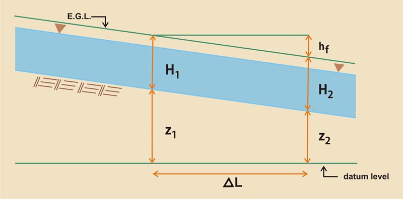
Eq. 16 2.02 The conservation of energy between the two cross sections is:
Eq. 17
Fig. 01
Eq. 18
Eq. 19
Eq. 20
2.03 Therefore, the distance increment along the channel is:
Eq. 21
Eq. 22 2.04 in which Sf is the average friction slope along the distance increment. 2.05 The sign of the distance increment is the sign of the denominator. In the case of the M2 profile, it is negative, meaning the calculation proceeds upstream from a control section.
2.06 Returning to our example, the specific head difference is:
Eq. 23
2.07 The distance increment ΔL is:
Eq. 22
Eq. 23
2.08 This is the distance increment between the depths of 3.0 m and 3.5 m. 2.09 Now, calculate the hydraulic variables for the depth of 4.0 m. Then, calculate the distance increment between 3.5 m and 4.0 m. 2.10 The new distance increment is:
Eq. 23
2.11 The cumulative distance between the depth of 3 m and the depth of 4 m is:
Eq. 23
2.12 This table shows the completed sample calculation of the M2 water-surface profile.
2.13 Note that by using 10 depth intervals, the total length of the M2 profile is 35200.8 m.
2.14 Yet the calculation is sensitive to the chosen number of depth intervals.
2.15 If we use 100 depth intervals, the total length of the profile is 65029.3 m. http://onlinecalc.sdsu.edu/onlinewsprofiles22.php
2.16 This stresses the importance of using very small depth intervals in order to guarantee accuracy. Fig. 01
Narrator: Victor M. Ponce Music: Fernando Oñate Editor: Flor Pérez
Copyright © 2011 Visualab Productions All rights reserved
|
