|
OPEN-CHANNEL HYDRAULICS: LECTURE 081 - CULVERT HYDRAULICS
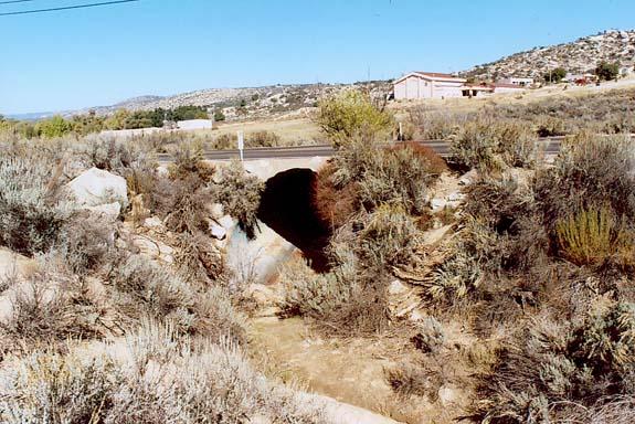
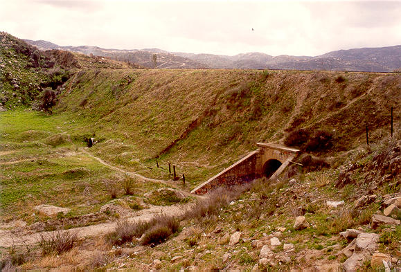
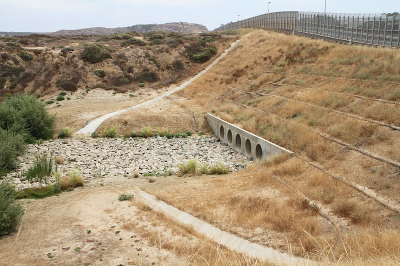
1. DEFINITION 1.01 A culvert is a short conduit placed under a fill, such as a highway embankment, or under a road, to convey streamflow. Fig. 01
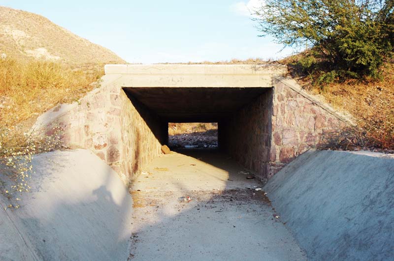
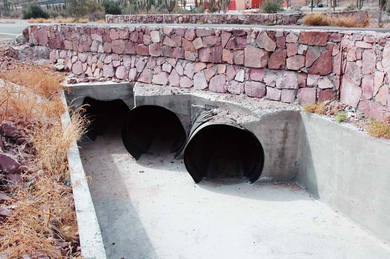
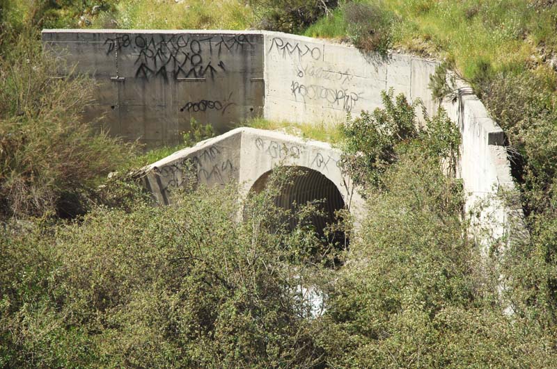
1.02 A culvert is engineered to pass the design discharge without overtopping. 1.03 The three most common culvert materials are concrete, corrugated aluminum, and corrugated steel. Fig. 02
Fig. 03
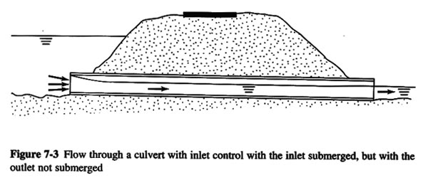
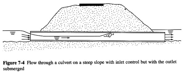
1.04 The flow in a culvert is a function of: 1. Cross-sectional size and shape. 2. Slope. 3. Length. 4. Roughness. 5. Entrance and exit characteristics. 1.05 Flow in a culvert may be either free surface or closed conduit, and may alternate between them in time and space. 1.06 The headwater is the depth above the culvert invert at the inlet. 1.07 The tailwater is the depth above the culvert invert at the outlet. 1.08 The headwater and tailwater depths determine whether the culvert will flow partially full or completely full. 1.09 The design objective is to select the most economical culvert size that will pass the design discharge without exceeding a specified headwater elevation. 1.10 The design depends on whether the culvert is under inlet or outlet control. 1.11 Inlet control occurs when the culvert is capable of conveying more flow than the inlet will allow. 1.12 Outlet control flow occurs when the culvert is capable of conveying less flow than the inlet will allow. 2. INLET CONTROL 2.01 Under inlet control, the control section is at the inlet, and the flow is supercritical immediately downstream. 2.02 Under these conditions, only the headwater depth and inlet configuration affect culvert performance. 2.03 The flow passes through critical depth at the inlet, and becomes supercritical downstream. 2.04 In the absence of high tailwater, the flow remains supercritical throughout, and control remains at the inlet. Fig. 04
2.05 When the flow at the inlet is open to the atmosphere, the flow condition resembles that of weir flow. 2.06 When the flow at the inlet is submerged, the flow condition resembles that of an orifice. 2.07 When the outlet is submerged due to high tailwater, a hydraulic jump will form inside the culvert, and control will shift to the outlet. Fig. 05
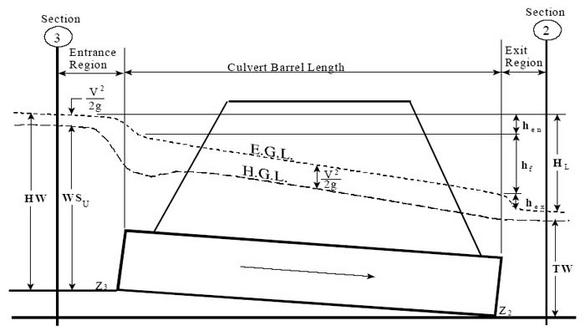
3. OUTLET CONTROL 3.01 Under outlet control, the control section is at the outlet, and the flow is either under pressure or subcritical immediately upstream. 3.02 Under these conditions, all factors affect culvert performance. These include: 1. Headwater depth, 2. Inlet configuration, 3. Barrel characteristics, including, area, shape, length, slope, and roughness, and 4. Tailwater depth. 3.03 Outlet control hydraulics is best described with pressure flow in the culvert barrel. 3.04 Therefore, a culvert under outlet control is calculated with the energy equation, resembling closed-conduit flow. 3.05 Typically, outlet control occurs when both inlet and outlet are submerged due to high headwater and high tailwater. 3.06 Outlet control may also occur when the culvert barrel has a mild slope and both headwater and tailwater depths are less than the culvert diameter. 3.07 In this case, the culvert operates as open-channel flow, either with uniform or gradually varied flow. Fig. 06
4. DESIGN PROCEDURE 4.01 Under inlet control, the aim is to calculate the headwater depth required to pass the design discharge. 4.02 Under outlet control, the aim is to calculate the energy loss required to pass the design discharge. 4.03 Given a design tailwater depth, and accounting for all head losses, an energy balance provides the headwater depth required to pass the required discharge. 4.04 In any case, the calculated headwater must not exceed a maximum allowable headwater elevation. 4.05 The trial-and-error procedure first assumes a culvert type and size, and proceeds to calculate a headwater elevation for the assumed size. 4.06 The procedure is repeated until the most economical size is found for which the calculated headwater elevation remains below the allowable maximum. 5. EXAMPLE 5.01 Design a culvert for the following conditions:
Eq. 1
5.02 The design elevation for the upstream pool is the roadway shoulder elevation, 110, minus the freeboard, 2, equal to 108 ft:
Eq. 2
5.03 Assume a circular concrete pipe, with square edge with headwalls. First assume outlet control. Fig. 06
Fig. 09
5.04 Calculate the outlet invert elevation:
Eq. 3
Eq. 4
5.05 Calculate the downstream pool elevation:
Eq. 5
5.06 The energy equation between upstream and downstream pools is:
Eq. 6 Fig. 07
5.07 The velocity in the upstream pool is zero. Likewise, the velocity dissipates to zero in the downstream pool. Thus, the energy balance is:
Eq. 7
Eq. 8
Eq. 9
5.08 The objective of the design is to find the diameter that will produce a total of 6.5 ft of head loss.
5.09 The sum of head losses is equal to the entrance and exit losses plus the head loss along the pipe:
Eq. 10
5.10 in which fD is the Darcy-Weisbach friction factor.
5.11 The relation between Darcy-Weisbach friction factor and Manning's n is:
Eq. 11
5.12 in which k is a unit conversion factor equal to 1 in SI units, and 1.486 in U.S. Customary units.
5.13 In U.S. Customary units, with g = 32.17 ft/s2, the relation between Darcy-Weisbach friction factor and Manning's n is:
Eq. 12
5.14 For a circular pipe:
Eq. 13
5.15 and the relation between Darcy-Weisbach friction factor and Manning's n for pipe flow is:
Eq. 14
5.16 In terms of Manning's n, the sum of head losses is:
Eq. 15 5.17 Assume the entrance loss coefficient Ke = 0.5, the expansion loss coefficient KE = 1, and with n = 0.013, and L = 200 ft:
Eq. 16 5.18 Now replace the velocity:
Eq. 17
5.19 and with Q = 200, and the flow area in terms of the culvert diameter:
Eq. 18
5.20 and g = 32.17 ft/s2:
Eq. 19
5.21 Solving this equation for D by trial and error:
Eq. 20
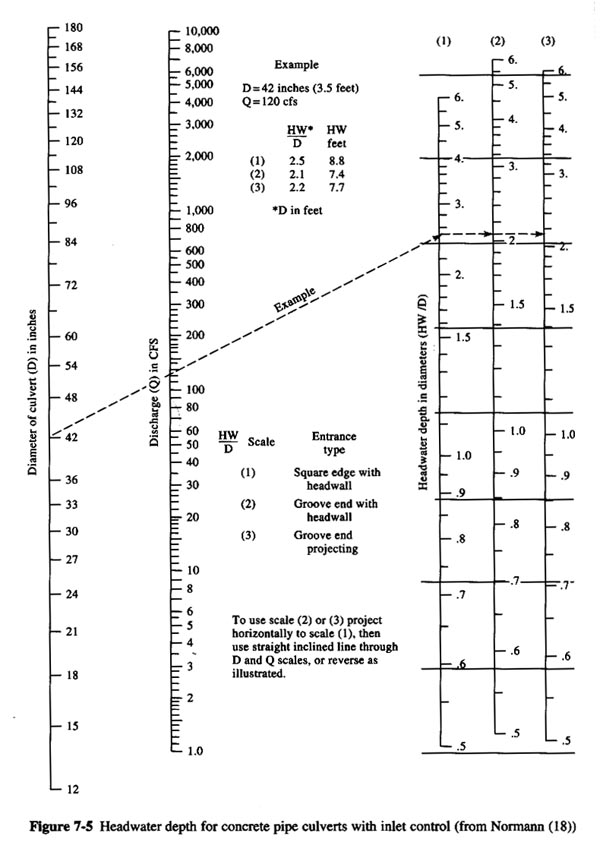
5.22 For design, choose the next larger size, that is 4.5 ft, or 54 inches. Enter the FHWA design nomograph with diameter 54 inches, design discharge Q = 200 cfs, and square edge with headwalls, to find the ratio of headwater depth to diameter:
Eq. 21 Fig. 08
5.23 The calculated headwater depth is:
Eq. 22 5.24 The upstream pool elevation is 100 + 9.9 = 109.9 ft, which exceeds the allowable value of 108 ft.
Eq. 23
5.25 Therefore, the culvert is undesized at 4.5-ft diameter. 5.26 Next, assume the next larger size, a 5-ft diameter. Enter the FHWA design nomograph with diameter 60 inches, design discharge Q = 200 cfs, and square edge with headwalls, to find the ratio of headwater depth to diameter:
Eq. 24 5.27 The calculated headwater depth is:
Eq. 25 5.28 The calculated upstream pool elevation is 100 + 8 = 108 ft, which matches exactly the allowable value of 108 ft.
Eq. 26
5.29 Therefore, the culvert is correctly sized at 5-ft diameter. 5.30 For this culvert flow, the normal depth is 3.28 ft, and the critical depth is 4.04 ft. Since the normal depth is less than the critical depth, the flow will remain supercritical in the culvert barrel.
Eq. 27 5.31 However, since the tailwater depth, 3.5, is slighly greater than the normal depth, 3.28, a small hydraulic jump is produced near the outlet. For the most part, the culvert will remain under inlet control.
Eq. 28 Fig. 10
Fig. 01
Fig. 02
Fig. 03
Fig. 04
Fig. 05
Fig. 06
Fig. 07
Fig. 08
Fig. 09
Fig. 10
Narrator: Victor M. Ponce Music: Fernando Oñate Editor: Flor Pérez
Copyright © 2011 Visualab Productions All rights reserved
|
