|
|
|
| 1. INTRODUCTION |
|
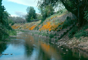
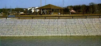
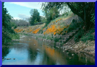
A gabion system is a wire-enclosed riprap consisting of mats or baskets fabricated with wire mesh (fig. 1), filled with small riprap, and anchored to a slope. Wrapping the riprap enables the use of smaller size riprap for the same resistance to displacement by water energy as larger unwrapped riprap. This is particularly advantageous when constructing rock lining in areas inacessible to trucks or large construction equipment. The wire basket also allows steeper (up to vertical) channel linings to be constructed from commercially available wire units or from available wire-fencing material. Do to their high shear strength, gabion systems provide a highly effective way to control erosion in earth-lined rivers and canals. They are normally designed to sustain channel velocities of 15 fps or higher. Gabions are constructed by individual units that vary in length from 6 ft to nearly 100 ft (gabion mats); therefore, applications can range anywhere from small ditches to large canals. Gabions can be completely vegetated to blend into the natural landscape (fig 2.). Gabion channels are a compromise between riprap and concrete channels. Therefore, they have some advantages over both, but at the same time they have some disadvantages. For instance, riprap channels can adjust to several grades, while concrete is not that forgiving. On the other hand, concrete can sustain higher speeds than riprap, which is limited to a maximum velocity of 16 fps. Riprap can be unstable on very steep slopes, especially when rounded rock is used. Although concrete channels can be designed to operate at high velocities, these must not exceed the permissible velocity of the recieving channel. Concrete channels are much more expensive to construct, and although they last longer than riprap or gabion channels, repair costs are likely to be high. Studies done at Colorado State University, Fort Collins show that roughness coefficient for riprap is approximately 0.047, while for the same rocks contained in wire mesh it is approximately .10, i.e. double that of riprap. This means that for any given hydraulic condition the average size of the rocks used in gabions is half that required in rip rap revetment. In the same way, if the same size rocks are used in rip rap and gabions the acceptable velocity for Reno matrtress and gabions is no less than 3-4 times that of that of the equivalent rip rap. Gabion channels with vegetation have the following advantages:
|
| 2. MANNING'S N |
|
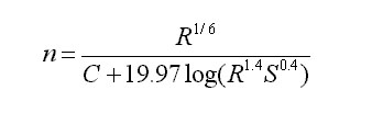
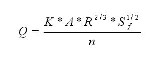
Manning's n or roughness coefficient for gabion channels with vegetations depends primarily on the submerged vegetation and the size of the stones used. There is no specific formula that can derive the roughness coefficient for this lining configuration but it can be derived knowing other Manning's n and relating them to this specific case. For specific gabions without vegetation manning's n ranges from .025 to .030. Manning's n for vegetated channels also vary depending on the type of soil, the amount of cover, resistance (Chezy coefficient) and retardance. Manning's n for vegetative linings is given by,
Where, R= Hydraulic radius, A/P, where A=Area and P=Wetted perimeter. C= Retardance class, depending on cover and condition. S= Energy slope of channel slope in uniform flow (m/m). The retardance coefficient C ranges from 15.8 for class A vegetation while class E vegetation has a C value of 37.7. Table 1 identifies the most frequent condition and covers found.
There is no specific formula for Manning's n for channels having riprap lining, gabion lining or concrete lining either. This is because a lot depends on the manufacturer and the sizes of the rock used or the mix. Following is a table that shows the most frequently used Manning's n for these linnings. As it is expected gabions are between rip rap and concrete linings.
It should be noted that rip rap channels have a very large variaty of manning's n because it depends on the diameter of the stone used and the channel flow depth aswell. When taking into account various linigs along the channel or if a certain cross section is composed of different linings we use,
to calculate manning's n, where nc, nl, nb, nr=Manning's n of the composite, left side slope, bottom and right side slope, respectively. WPl, WPb, WPr, WPsubt= Wetted perimeter of the lift side slope, bottom, right side slope, and total channel respectively. The problem lies when we have a gabion channel with vegetation on the same location as can be seen in fig. 5. Here we can only speculate through intuition and experience what is the manning's n to be used. Another suggestion is to use Eq. 2 by avereging the nl, nb and nr by relation of the percentage they cover.
|
|
| 3. GABION FACTS |
|
The procedure for placing and filling gabions can be summarized as follows: assembling the individual units before placing
(fig. 6),
placing them and wiring them together, filling the units with rocks (fig. 7) and closing and wiring down the lids
(fig. 8). How to place the gabions down basically depends on the type of lining present; either dry (fig. 9) or under water (fig 10.). Linings laid in dry conditions are placed directly on a stable slope that should not be too steep as to cause the revetment to slide. The units are normally laid down on the slope of the bank, at right angles to the current. However the units on the bed itself should be laid in the direction of flow. When constructing a lining under water, dumping riprap is challenged by the many uncertainties, since it is very difficult to obtain a uniform distribution of the material over the whole area to be protected. In order to reduce the risk the amount of rocks dumped has to be increased by 50%. This problem does not arise when dealing with gabions since the structure is pre-assembled and with fix thickness. The gabions can be placed using cranes or pontoons (fig. 11). It should be noted that the stability of gabion linings does not only depend on the strength of the mesh, but also on the thickness of the lining and the grading of the stone fill. Once the average water velocity is known, these parameters can be selected. It is essential for the longevity of the revetment that the mesh be protected against corrosion; therefore the gabions are constructed from wires with heavy zinc content and PVC coating. Where the natural bank exceeds a 1:15 gradient some kind of support in the form of gabion retaining walls should be provided |
| 4. DESIGN CRITERIA |
|
The two primary elements in drainage way design are cross-section (fig. 12) shape and lining. The most typical cross sections are triangular (v-shped), parabolic and trapezoidal. Lining is determined by erosion resistance and drainage requirements. All-vetgetated linings are appropiate for low velocities. Paved linings may be used for soil-water interfaces where the soil conditions, and groundwater conditions are such that the soil may erode under design flow conditions. Generally velocities over five (5) per second will require lined waterways. For design purposes, uniform flow conditions are usually assumed with energy slope (Sf) approximately equal to average bed slope (So). This allows the flow conditions to be defined by a unifrom flow equation such as Manning's equation (Eq.1). Supercritical flow creates sufraces waves that are approaching the depth of flow. For very steep channel gradients, the flow may splash and surge in a violent manner and special considerations for freeboard are required. An iterative approach ca be used to get the required manning's n, given the design discharge (Q), cross-sectional geometry and bed slope (S), one can intechange the n until the required yo is reached. Considerations made when determining physical size and cross-sectional shape of the channel must be approached between available Real Estate, Rinancial Limitations, Public Safety, Environmental Preservation, Aesthetics and anticipated future flow Discharges. Once the basic hydraulic and physical characteristics of the channel have been determined, the selection and stability analysis can be made. Generally, a 10-year up to a 100-year storm is used to determine capacity, while the 2-year storm is used to check ditch stability. After vegetation is fully developed, the channel is considered stable and capacity become more critical. The design discharge is generally calculated using the rational method or other computarized models. (i.e. HEC-RAS). Bascically, waterways should be designed so that the expected flow velocity from the design storm does not exceed the permissible veolicty for the type of lining used. It is also important to check outlets for stability. Excessive velocities or grade chabges may require protective or stabilizin structures, transition sections, or energy disipators to prevent erosion or scour. Gabion thickness depends on manufacturer specifications and stone sizes, which may range from 4 to 8 inches. When selesting the stone sizes one has to be aware that these types of linings are subject to clogging by sediment. When the Froude number given by
where, V= Mean flow velocity g= Gravitational acceleration y= hydraulic depth, defined as the flow area (A) divided by the mean top water surface width (Wsurf). approaches critical (between 0.8 and 1.2), channel flows may become unstable, and the designer should consider modifying the channel slope or bottom width.
|
| 5. DESIGN EXAMPLE |
|
The following example is for use on straight trapezoidal channels exhibiting steady, uniform flow conditions (no flow obstacles, bends, inlet pipes, etc. are considered). Given:
Q= 700 m3/s 1. Let us assume that a requirement for a project is to have a gabion channel with vegetation along the reach. Since there is no given manning's n for this case, an interpolation among the known values of vegetation and gabions without vegetation should be made. For instance let us assume that we have a normal gabion system with a manning's n of .027 and vegetation in the form of buffalo grass has grown around it. By refering to Tabe 1. and Eq 1. we can say that the manning's n for the vegetation is .033. Now using Eq. 2 where, nl and nr are both .030 and nc is .04 assuming the botton has a riprap like lining, gives us a composite n of .034. 2. After selecting the manning's n by assuming a certain cover and rock size we compute the normal depth by solving the manning's equation
where, Solving this equation for yo using the quadratic formula gives us a normal depth of 3.83 m. 3. By calculating the cross sectional flow area which is 86.8 m we can compute the velocity of the flow, 8.06 m/s. 4. Typically all channels should exhibit a freeboard area. This "freeboard" is simply an allowance for design flows to be modestly exceeded as to prevent flows from overtopping the sides of the channel. In most cases, the physical depth of the channel should be 1.5 times the flow depth. In this case 1.5*3.83= 5.75 m < 6 m. If this were not the case a different channel width (B) should be selected. 5. To evaluate the flow stability by determining the Froude number we use Eq. 3 which gives us 1.52 which is > 1.2, if this were not the case a different channel width (B) should be selected. 6. For many engineering applications, the quantified required property is compared to the actual property by means of a Factor of Safety. FS= Actual/Requiered. A FS greater than 1.0 indicates that the material property exceeds the requirement; however, it provides no allowance for incorrect design assumptions or material variability. A FS of 1.5 is a good starting point. We can check the stability of the channel by comparing the channel area with the flow area, 162/86.8 we get 1.87 which indicates we are above the FS required.
|
| 6. SUMMARY |
|
El Niño is a global climatic anomaly caused by a weakening of the trade winds along the tropical Pacific, strong events occur at 8- to 15-year intervals. El Niño can alter the magnitude and frequency of floods and droughts. Typically, if a region floods, other regions will experience drought. Floods and droughts can lead to extensive damages to life and property. El Niño can also affect biota in diverse ecosystems, including terrestrial and marine. |
|
http://ponce.sdsu.edu/manningsn_hydroecological.html
|
020627
|
